PC
BOARDS
Service Manual M4 - M10
22.10.2001
Page
89
C29
C
30
C
32
C33
C35
C36
C38
C39
C41
C
42
C
44
D
4
D5
D
21
D22
D
23
D
24
H8
H10
H13
H15
R14
R21
R2
2
R23
R2
4
R2
5
R2
6
R2
7
R3
1
R3
3
R3
7
R
38
R
39
R41
R42
R4
4
R4
5
R4
9
R5
0
R5
1
R5
5
R5
6
R5
7
R6
1
R
62
R
63
R65
R66
R68
R6
9
R7
3
R7
4
R75
R79
R8
0
R8
1
R8
5
R
86
R
87
R
89
R
90
R92
R93
R117
V5
V6
V8
V1
2
V1
3
V1
5
V17
V2
1
V2
2
V23
V24
V26
V2
8
V2
9
V3
1
V33
V3
7
V3
8
V39
V40
V42
V43
V4
4
V4
5
V4
7
V49
V5
2
V6
1
X9
X10
X1
1
X1
2
X13
X1
4
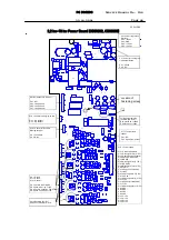
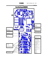
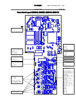
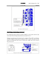
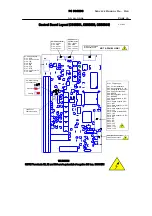
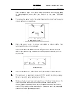
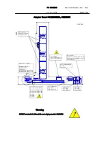
Gate Resistors (Rx, Ry)
Values on table GATE.XLS
X9 = Gate U
X11 = Gate V
X13 = Gate W
Pin 1: emitter, lower leg DC-
Pin 2: gate, lower leg +/-15V
Pin 4: emitter, upper leg FLOATING!
Pin 5: gate, upper leg +/-15V
1
2
4
5
Gate resistors on the Power board.
9.2.6.3 Voltage related settings on the board
For reliable operation with various types of IGBTs in units, gate resistors have
to be selected according instructions as in section 9.2.6.2.
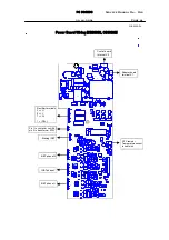
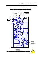
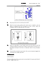
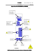
Voltage programming will be done by the resistors R9 and R19 according to
nominal voltage the board will be installed in. Both resistors are placed on the
board by manufacturer and in prior to determine usage, one of the resistors
has to be cut off.
R 9 X O
R 18 O
X
400
V
500
V
X = CU T O FF
O = P LA C ED O N
C
22
C
23
C
24
C
25
C
26
C
27
C4
8
C
52
H18
R7
2
R1
0
2
R
10
9
R
11
0
R1
1
1
R119
V59
V60
X1
X5
X6
X7
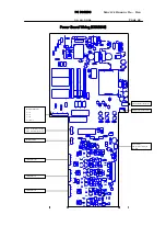
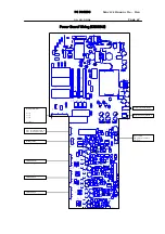
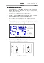
Voltage program m ing
resistors (R9, R18)
R18 placed on => 400V
R9 placed on =>500V
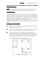
X 1
Location of
Fastening screw
S ettings on the Pow er board according to nom inal operation voltage.


