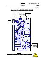
PC
BOARDS
Service Manual M4 - M10
22.10.2001
Page
108
9.5.4 Schematic diagrams
NOTE! Schematic diagrams are not distributed to Service Centres. In case of
schematic diagrams are needed these can be requested from Producer.
9.5.5 Troubleshooting
Due to simplicity of the board, there is no advanced troubleshooting
techniques required.
In case of malfunction, check all connectors and soldered junctions from
weak connection.
9.5.6 Spare parts
Branching boards.
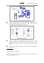
Detailed information for the spare parts is available from spare parts lists in
section “SPARE PART LIST”.
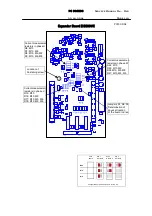
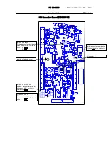
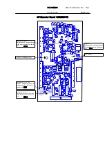
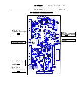
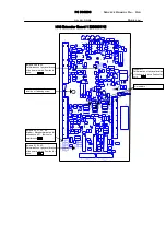
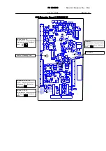
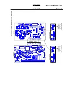
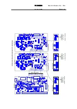
9. 6 Extender (Expander) board
9.6.1 Description
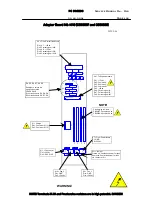
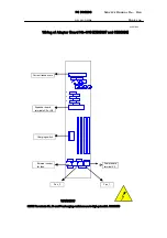
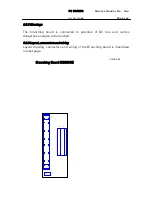
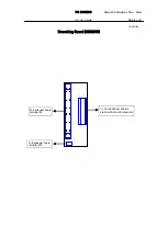
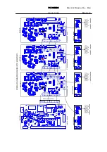
Branching board is used to units constructed into multiple bay construction
such as units in mechanical frames M8 - M10. Function of the board is to
share logic level gate signals to each block in construction. Signals are
delayed on the boards for simultaneous gating of the IGBTs. Due to relatively
long signal transmission line signal clarity and signal proneness are coming
to be an issue. To achieve proper signal existence, such as levels and proper
timing, signal is filtered, buffered and delayed on the Extender board.
Currents measured from the each output phases of each blocks are
processed on the Extender board by dividing the measured current in block by
number of the blocks in the unit and finally summed to get value of signal to
correspond total output current of the drive. The peak values of the current
signals are measured for over current protection.
Signals of the DC bus voltage as well as operation temperature of each block
are measured individually and conducted via Extender board to the Control
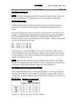
board. Few resistor settings are required to set board to be used in various
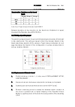
types of drives. Also settings for the board by the jumpers have to be done to
determine proper summing procedure of measured signals.

