PC
BOARDS
Service Manual M4 - M10
22.10.2001
Page
120
9.6.4 Schematic diagram
NOTE! Schematic diagrams are not distributed to Service Centres. In case of
schematic diagrams are needed these can be requested from Producer.
9.6.5 Troubleshooting
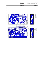
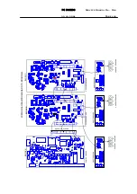
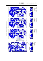
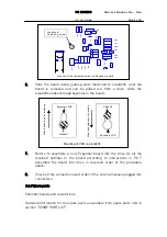
Trouble shooting for the Extender board will be carried out by measuring
signals from the terminals X5 and X6 on the board, following procedure
below.
Connect signal source 1Vrms (sinusoidal, or pulsetrain) to terminals X5 and
X6 pins 6, 7 and 8 on the Extender board (common at base plate of regulator
N4). Repeat procedure for each block in construction, if more than one.
Measure signals from terminal X2 pins 7, 8 and 9 to (DC-). Value of the signals
at terminal X2 shall be as follows:
M8
U(X2) = 1/2 * U(X5, X6)
M9
U(X2) = 1/3 * U(X5, X6)
M10 U(X2) = 1/4 * U(X5, X6)
Look at value on monitoring display n3 (motor current) and compare it to
nominal rated current (constant torque rating) of the particular drive. Signal
1Vrms represents nominal value of the particular drive and the value on the
display should be as nominal.
NOTE! Unit has to be powered up by the method, where DC bus of the drive
has not been powered up. Only control circuitry is powered up and operating.
For details of using external power supply, look at section 7.3.2.
9.6.6 Setting of current measurement circuitry
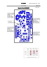
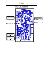
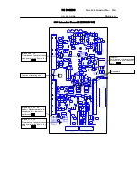
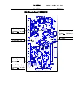
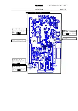
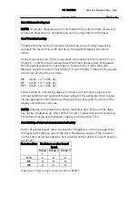
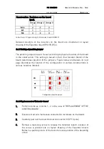
On the Expander board, there are twelve (12) resistors in three groups to be
configured according to type of the drive. Resistance values of the resistors
are the same and while settings, only quantity of the resistors in each group is
significant.
Construction Resistors on the board
(pcs).
Group
1
Group 2 Group 3
M10 4 4 4
M9 3
3 3
M8 2
2 2
Table 9.6.6.1 Programming for Expander board CB00019

