PC
BOARDS
Service Manual M4 - M10
22.10.2001
Page
121
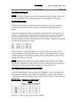
Construction Resistors on the board
(pcs).
Group
1
Group 2 Group 3
M10 2 2 2
M9 1
1 1
M8 0
0 0
Table 9.6.6.2 Programming for Extender board CB00119
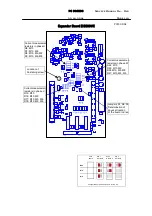
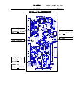
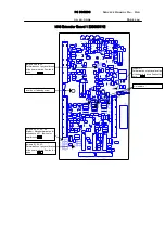
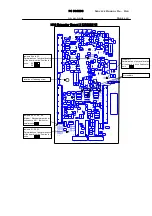
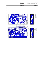
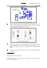
Detailed locations of the resistors on the board are illustrated on layout
drawing of the Expander board (PC19C.DS4).
9.6.7 Setting of position jumper
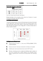
The position jumpers have to be set according to physical location of the board
in the construction. This setting is based on fact, that location (block) of the
board determines position of the jumpers. Figure below and details on next
page illustrates the relation of the configuration in various constructions in
various locations (blocks).
M10
M9
M8
Exp. 1
in block B
Exp 2
in block C
Exp 3
in block D
Cont
board
Configuration of position jumper
9.6.8 Replacement of Extender board
1.
Perform items as in items 1 - 2 in the case of “REPLACEMENT OF THE
CONTROL BOARD”.
2.
Disconnect all wire harnesses connected to terminals on the board.
3.
Carefully pull out the board to board connector X3 (2*13 pins).
4.
Remove a fastening screw to release the Extender board. Location of
the screw is pointed out on layout drawing of the Expander board.
Below is a partial picture of the board to locate position of the fastening
screw.

