12 • vacon
layout and connections
Tel.+358 (0)201 2121 • Fax +358 (0)201 212 205
3
3.5
Bus Biasing
Bus biasing is required to ensure faultless communication between devices at RS-485 bus. Bus bias-
ing makes sure that the bus state is at proper potential when no device is transmitting. Without bias-
ing, faulty messages can be detected when the bus is in idle state. RS-485 bus state should be
n0,200..+7V or –0,200..-7V. Illegal bus state is <200mV..-200mV.
Number of nodes
Bias resistance
2-5
1.8 kohm
5-10
2.7 kohm
11-20
12 kohm
21-30
18 kohm
31-40
27 kohm
Table 4. Bias resistor size vs number of node
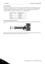
Fail safe
biasing in OPTC2 option board
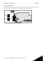
Connect resistor biasing resistors between pins #2 and #4 as well as pins #3 and #5 as shown in pic-
ture.
Matters related to this are discussed in the application note
Failsafe Biasing of Differential Buses
(an-
847.pdf) published by National Semiconducto
DATA-
DATA+
5
1
2
3
4
5
A
B


