background image

page 43 of 56

 Assembling the pump heads

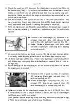
 Place the pump in a way that the pump head to be assembled is at the 

top. Support the pump appropriately.

 Bring the diaphragm (F) into a position in which it is in contact with the 

housing (J) and centered with respect to the bore.

 Place the head cover (D) over the diaphragm. Check for its correct 

orientation by aligning it beforehand with the housing cover which has 

to be put over it later on.

+

 Pay attention that the diaphragm (F) stays positioned centrally so that 

it will become clamped uniformly between housing (J) and head cover 

(D). 

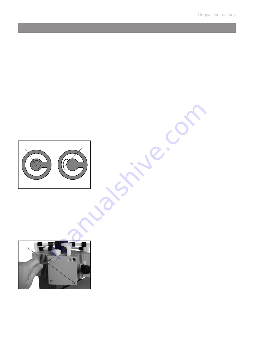
 Place the valves (B) and the O-rings (C) at 

their respective positions on the head cover 

(D). 

+

 Make sure that the valves are correctly 

seated. See figure for the correct position of 

the valves: Valves at the outlet with round 

centered opening (S) under valve; valves at 

the inlet with kidney-shaped opening (T) be-

side valve.

 Place the housing cover (A) with housing 

cover insert onto the head cover.

S

T

 Loosely screw in the Allen head screws (R) 

of the housing cover in a start pattern with a 

5 mm wide Allen key, then tighten.

+

 Recommended torque: 8.9 ft

.

lb

(12 Nm).

R

Summary of Contents for ME 16C

Page 1: ...page 1 of 56 Instructions for use Technology for Vacuum Systems Chemistry diaphragm pumps ME 16C MZ 8C MD 8C MD 12C MV 10C...

Page 2: ...phragm pump before leaving our factory is tested intensively including an endurance run of 14 hours Any faults even those which oc cur rarely are identified and can be eliminated immediately After com...

Page 3: ...equired measures must be applied Safety instructions for vacuum equipment FR Attention Le mode d emploi pr sent n est pas disponible dans toutes les langues d Union Europ enne L utilisateur ne doit me...

Page 4: ...tiende este manual En este caso se debe disponer de una traducci n t cnicamente correcta del manual completo El manual debe ser le do y entendido completamente y deben aplicarse todas las medidas de s...

Page 5: ...nte letto e compreso prima di operare con lo strumento e devono essere applicati tutti gli accorgimenti richiesti Istruzioni di sicurezza per apparecchi a vuoto JP KR LT D mesio is vadovas n ra pateik...

Page 6: ...o ci przeczytana i zrozumiana przed podj ciem pracy z urz dzeniem oraz nale y podj wszystkie niezb dne kroki zwi zane z prawid owym uzytkowaniem Wskaz wki bezpiecze stwa do urz dze pr niowych PT Aten...

Page 7: ...opravljene pa moraja biti tudi vse potrebne meritve Varnostni nasveti za vakuumske naprave SK Upozornenie Tento manu l nie je k dispoz cii vo v etk ch jazykoch E U vate nesmie obsluhova zariadenie pok...

Page 8: ...s 25 Abbreviations 25 Pump parts 26 Use and operation 28 Installing a pump in a vacuum system 28 During operation 29 Important notes regarding the use of gas ballast 31 Shutdown storage 32 Accessories...

Page 9: ...om the pump and the pumped substances VACUUBRAND disclaims any liability for inappropri ate use of these pumps and for damage from failure to follow instructions contained in this manual This manual i...

Page 10: ...moderate injury NOTICE is used to address practices not related to personal injury Caution Hot surface Disconnect equipment from AC power NOTICE Formatting used in this manual Note The signal word pan...

Page 11: ...cies Replace the protective caps if the equipment is not used immediately Store the equipment in dry and non corrosive conditions see also Technical data pg 23 Do not use any damaged equipment Use the...

Page 12: ...er the pump Do not pump liquids Ensure that the pump is chemically resistant to the pumped substances prior to operation Use the equipment only as intended that is for genera tion of vacuum in vessels...

Page 13: ...le Check that all fittings are secure Ensure a stable position of the pump without any me chanical contact other than the pump feet Comply with maximum permissible pressures at in let and outlet and w...

Page 14: ...rfaces e g rubber foam during operation This may reduce or block the fans air supply Check fan regularly for dust dirt Clean fan guard grill if necessary to avoid a reduction of ventilation Use only h...

Page 15: ...ype and model Directive EN 61010 1 gives in detail the conditions under which the equipment can be operated safely see also IP degree of protection Technical data pg 23 Operating conditions These pump...

Page 16: ...may lead to increased temperatures even to the point of exceeding the maximum permitted temperatures Check the inlet and outlet of the pump if there is a danger of forming deposits inside the pump e g...

Page 17: ...or gas ballast or venting if necessary Drain appropriately or otherwise remove any poten tially explosive mixtures at the outlet of the pump or dilute them to non explosive concentrations Never operat...

Page 18: ...of the pumped substances or the environment Ensure that no parts of your clothing hair or fingers can be caught or drawn in at the inlet of the pump Never insert fingers or drop any other object into...

Page 19: ...ump Maintenance and repair In order to comply with laws occupational health and safety regulations safety at work law and regulations for environmental protection vacuum pumps components and measuring...

Page 20: ...regularly Never operate a defective or damaged pump Check every motor capacitor regularly by measuring its capacity and estimating its time in operation Re place old capacitors early enough to preven...

Page 21: ...explosive atmo spheres caused by gases vapors or mists normally don t occur or if they do occur are likely to do so only infrequently and for a short period only Equipment in this category ensures the...

Page 22: ...mp achieves its specified ultimate vacuum is the pump s leak rate low enough to en sure that no explosive atmospheres will occur in the interior of the equip ment After any intervention at the vacuum...

Page 23: ...n sea level ft m 6500 2000 Rated motor power hp kW 0 52 0 39 No load speed 50 60 Hz rpm 1500 1800 Maximum permissible range of supply voltage Attention Observe specifications of rating plate 100 V 10...

Page 24: ...x 11 6 490 x 237 x 294 Weight approx lbs kg 55 1 25 0 Type MD 12C MV 10C Maximum pumping speed 50 60 Hz ISO 21360 cfm m3 h 4 9 5 2 8 3 8 9 4 1 4 4 7 0 7 5 Ultimate vacuum absolute without gas ballast...

Page 25: ...nutes 75 Torr 100 mbar low gas load 14 F to 176 F 10 C to 80 C Wetted parts Components Wetted materials Outlet ETFE Inlet Stainless steel Diaphragm clamping disc ETFE carbon fiber reinforced Diaphragm...

Page 26: ...C Position Component 1 Inlet 2 Outlet 3 ON OFF switch 4 Power connection 5 Handle 6 Pump rating plate 7 Fan 8 Distributor at the inlet 9 Distributor at the outlet 10 Gas ballast valve Pump parts ME 16...

Page 27: ...page 27 of 56 ME 16C MZ 8C MD 8C MV 10C MD 12C MV 10C MD 12C ME 16C MZ 8C MD 8C Fittings at inlet side Fittings at outlet side...

Page 28: ...lters You must ensure their suitability concerning gas flow chemical resis tance and resistance to clogging prior to use Make sure ventilation is adequate especially if the pump is installed in an enc...

Page 29: ...to isolate the pump from the vacuum application This is to allow the pump to warm up before pumping condensable vapors and to clean the pump after use before it is switched off When assembling ensure...

Page 30: ...etc let the pump run with gas ballast to help purge any condensation in the pump Prevent internal condensation transfer of liquids or dust The diaphragms and valves will be damaged if liquids are pump...

Page 31: ...n inert gas for the gas ballast This constitutes a risk of significant damage to equipment and or facilities a risk of per sonal injury or even loss of life Make sure that air gas intake through the g...

Page 32: ...reases the solvent recovery rate at the exhaust waste vapor con denser see Accessories pg 33 Shutdown storage The pump can be switched off under vacuum Short term Has the pump been exposed to condensa...

Page 33: ...2 KF 25 1000 mm 20686033 Vacuum hose caoutchouc 10 mm ID 20686002 Metal hose stainless steel KF DN 25 1000mm 20673337 Vacuum controller CVC 3000 20683160 100 230 V 50 60 Hz Separator inlet 20699980 sm...

Page 34: ...e VCL 01 20677106 VACUU LAN shut off manual flow control module VCL 02 20677107 VACUU LAN automatic control module VCL B 10 20677208 VACUU LAN manual flow control automatic control module VCL B 11 206...

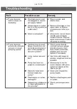
Page 35: ...sual pumping speed Centring ring at small flange connection not correctly positioned or leak in the pipeline or vacuum system Check pump directly connect vacuum gauge directly at pump inlet then check...

Page 36: ...only Fault Possible cause Remedy Pump too noisy Atmospheric or high pressure at the pump inlet Connect hose or silencer to pump outlet Be careful not to cause outlet over pressure especially with con...

Page 37: ...that the pump is decontaminated before maintenance Avoid the release of pollutants Never operate a defective or damaged pump Take adequate precautions to protect people from the effects of dangerous...

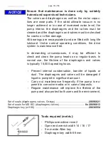
Page 38: ...be efficient to check and clean the pump heads on a regular basis In normal use the lifetime of the diaphragms and valves is typically 15 000 operating hours Prevent internal condensation transfer of...

Page 39: ...ves C O rings D Head cover E Diaphragm clamping disc with square head screw F Diaphragm G Diaphragm support disc H Washer Pump head parts I Connecting rod J Housing K Cover plate L Manifold cover only...

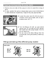
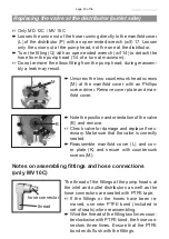
Page 40: ...he pump appropriately Loosen the union nuts N of the hose con nections at the pump heads with an open ended wrench w f 17 Turn the fittings Q with an open ended wrench w f 14 at outlet w f 16 to detac...

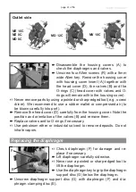
Page 41: ...use a rubber mallet or compressed air to be blown carefully into port Remove the head cover D carefully from the housing cover Note the position and orientation of the valves B and remove them Replace...

Page 42: ...osition diaphragm with pale side towards diaphragm clamping disc facing pump chamber Make sure that the square head screw of the diaphragm clamping disc is correctly seated in the guide hole of the di...

Page 43: ...ragm F stays positioned centrally so that it will become clamped uniformly between housing J and head cover D Place the valves B and the O rings C at their respective positions on the head cover D Mak...

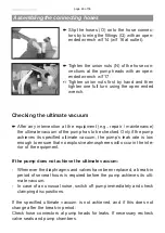
Page 44: ...correctly calibrated Measure the vacuum at the inlet port marked IN A vacuum of less than 120 mbar should be achieved If the reading is higher recheck the pump chamber and make sure that the valves a...

Page 45: ...head during reassem bly a leak may result M Note the position and orientation of the valve B and remove Check valve for damage and replace if nec essary Make sure that the valve is correctly seated R...

Page 46: ...several hours is required before the pump achieves its ulti mate vacuum In case of an unusual noise switch off pump immediately and check clamping disc positions If the specified ultimate vacuum is n...

Page 47: ...ed Also decontaminated devices must not returned to VACUUBRAND due to a residual risk The same conditions apply to on site work No repair maintenance return or calibration is possi ble unless the corr...

Page 48: ...e parts for cosmetic reasons at your request and at your expense Before returning the device Pack the device properly if necessary please order origi nal packaging materials at your costs Mark the pac...

Page 49: ...rmal wear and tear of wearing parts such as diaphragms seals valves vanes condensers oil and the breakage of glass or ceramic parts for the consequences of chemical electrochemical or electrical influ...

Page 50: ...for reason of appearance repaint and replacement at customer s expense yes no 12 Legally binding declaration We assure for the returned device that all substances which have been in contact with the d...

Page 51: ...52 20710200 20710201 20710202 Seriennummer Serial number Num ro de s rie Siehe Typenschild See rating plate Voir plaque signal tique Angewandte harmonisierte Normen Harmonized standards applied Normes...

Page 52: ...Protection Use Period EPUP EPUP defines the period in years during which the hazardous substances contained in electrical and electronic products will not leak or mutate under normal operating condit...

Page 53: ...isclosures in the above table the subassemblies are not intentionally manufactured or formulated with lead Pb mercury Hg cadmium Cd hexavalent chromium Cr VI polybrominated biphenyls PBB and polybromi...

Page 54: ...page 54 of 56...

Page 55: ...page 55 of 56...

Page 56: ...ore strictly the users responsibil ity to very carefully check the application of these data to their specific requirements No claims arising from the information provided in this lit erature will con...

Reviews: