page 79 of 152
The vacuum gauge was adjusted using factory standards,
which are traceable through regular calibration in an ac-
credited laboratory (DAkkS calibration laboratory) to the
German national pressure standard. Depending on the
process and/or accuracy requirements, check the adjust-
ment and readjust if necessary. For readjustment, the
device has to be adjusted both at atmospheric pressure
as well as under vacuum but only if the reference pres-
sures are known with certainty. The adjustment mode can
be activated only if the process control is inactive. Press
”START/STOP” key, if necessary. In the range between 15
to 525 Torr (20 to 700 mbar) no adjustment is possible;
---- Torr is displayed.
NOTICE
Adjustment at atmospheric pressure
An adjustment at atmospheric pressure is only
possible if the pressure is higher than 525 Torr
(700 mbar).
Vent the measurement connection of the CVC
3000 and/or the vacuum system. Make sure
that the pressure transducer is at atmospheric
pressure.
➨
In ”
Configuration
” menu, select program ”
Adjustment
” at the controller.
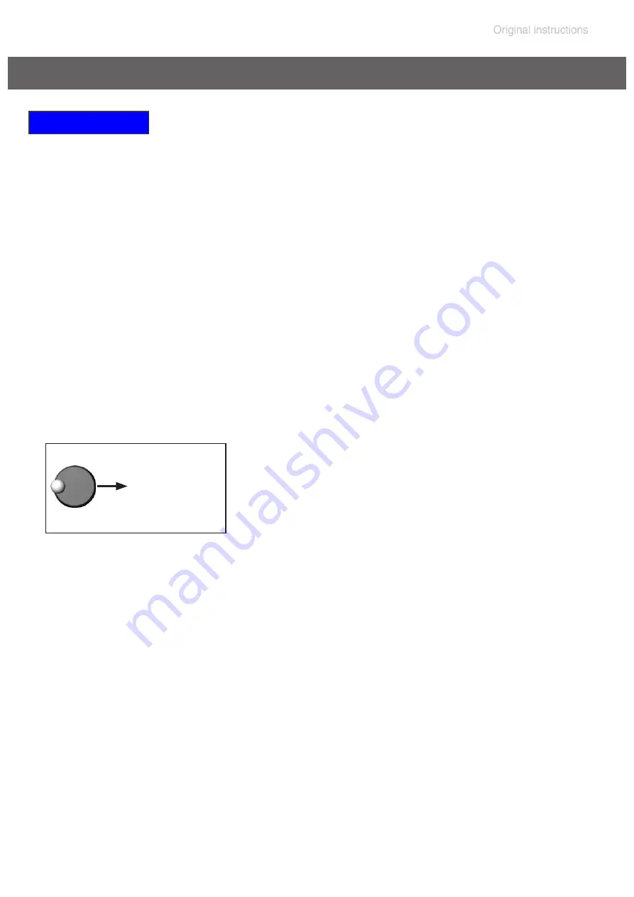
➨
Use the selection knob to adjust the reading to the current atmospheric
pressure.
➨
Press the selection knob to confirm.
1013 mbar
Note:
To determine the actual atmospheric pressure, use an accurate
barometer or get accurate reading from the weather service, or a nearby
airport or other reliable source (taking into account the difference in alti-
tude between the source and the laboratory).
Readjustment of CVC 3000
Summary of Contents for MV 10C NT VARIO o.C.
Page 34: ...page 34 of 152 1 8 2 9 18 PC 3012 NT VARIO EK Peltronic 12 11 16 8 17 3 4...
Page 104: ...page 104 of 152 2 3 size 1 2x 4...
Page 105: ...page 105 of 152 6 5 7 4 4x...
Page 106: ...page 106 of 152 9 8 1 2 2 5 mm 2 5 mm 10 ME 16C NT VARIO MD 12C NT VARIO MV 10C NT VARIO...
Page 108: ...page 108 of 152 12 Emission condenser Peltronic 4 4x 11A 13 4 2x...
Page 109: ...page 109 of 152 15 14 4 4x Don t loosen this screw 15A 16...
Page 110: ...page 110 of 152 16 17 5 2x 15A 1 2 3 1 4 1 4 3 2x 5...
Page 111: ...page 111 of 152 19 20 18 5 2x...
Page 113: ...page 113 of 152 21 2 5 mm Replacing the diaphragms 22 23 696867 696839 Clean 5 8x...
Page 114: ...page 114 of 152 24 25 26 1 2...
Page 115: ...page 115 of 152 27 3 28 29 Pay attention to number of washers...
Page 118: ...page 118 of 152 36 37 38 Clean...
Page 119: ...page 119 of 152 39 40 41 IN IN EX EX 696867 696839 4x...
Page 120: ...page 120 of 152 42 43 44 IN EX T20 4x 2 2 ft lbf 3 Nm...
Page 121: ...page 121 of 152 45 46 47 Maintain all pump heads in the same way...
Page 125: ...page 125 of 152 2 size 2 2x 3 4A Version A valve 24 4 mm...
Page 126: ...page 126 of 152 5A 696839 24 4 mm 26 mm 4B 5B 696839 37 mm 40 mm Version B valve 37 mm...
Page 127: ...page 127 of 152 6 7 size 2 2x 7A ME 16C NT VARIO MD 12C NT VARIO MV 10C NT VARIO size 2 2x...
Page 129: ...page 129 of 152 49 Assembling the pump housing 50 51 5 2x 8 9 ft lbf 12 Nm...
Page 130: ...page 130 of 152 52 53 54 5 2x 8 9 ft lbf 12 Nm...
Page 131: ...page 131 of 152 55 55A 1 2 3 3 2x 55A 56...
Page 132: ...page 132 of 152 56 4 4x 3 7 ft lbf 5 Nm 58 4 4x 3 7 ft lbf 5 Nm 57 4 2x 3 7 ft lbf 5 Nm...
Page 133: ...page 133 of 152 59 60 61...
Page 135: ...page 135 of 152 62 63 4 4x 3 7 ft lbf 5 Nm 64...
Page 136: ...page 136 of 152 65 66 67 size 1 2x...
Page 137: ...page 137 of 152 68 69...
Page 140: ...page 140 of 152 4 638821 638821 5 6...
Page 141: ...page 141 of 152 7 T20 4x size 1 4x 8...
Page 149: ...page 149 of 152...
Page 150: ...page 150 of 152...
Page 151: ...page 151 of 152...


