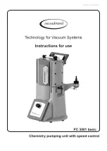
background image

page 1 of 53

Instructions for use

Technology for Vacuum Systems

Chemistry pumping unit with speed control

PC 3001 basic

Summary of Contents for PC 3001 basic

Page 1: ...page 1 of 53 Instructions for use Technology for Vacuum Systems Chemistry pumping unit with speed control PC 3001 basic...

Page 2: ...phragm pump before leaving our factory is tested intensively including an endurance run of 14 hours Any faults even those which oc cur rarely are identified and can be eliminated immediately After com...

Page 3: ...equired measures must be applied Safety instructions for vacuum equipment FR Attention Le mode d emploi pr sent n est pas disponible dans toutes les langues d Union Europ enne L utilisateur ne doit me...

Page 4: ...tiende este manual En este caso se debe disponer de una traducci n t cnicamente correcta del manual completo El manual debe ser le do y entendido completamente y deben aplicarse todas las medidas de s...

Page 5: ...nte letto e compreso prima di operare con lo strumento e devono essere applicati tutti gli accorgimenti richiesti Istruzioni di sicurezza per apparecchi a vuoto JP KR LT D mesio is vadovas n ra pateik...

Page 6: ...o ci przeczytana i zrozumiana przed podj ciem pracy z urz dzeniem oraz nale y podj wszystkie niezb dne kroki zwi zane z prawid owym uzytkowaniem Wskaz wki bezpiecze stwa do urz dze pr niowych PT Aten...

Page 7: ...opravljene pa moraja biti tudi vse potrebne meritve Varnostni nasveti za vakuumske naprave SK Upozornenie Tento manu l nie je k dispoz cii vo v etk ch jazykoch E U vate nesmie obsluhova zariadenie pok...

Page 8: ...ump in a vacuum system 28 During operation 30 Important notes regarding the use of gas ballast 31 Shutdown storage 32 Accessories 34 Troubleshooting 35 Replacing diaphragms and valves 37 Cleaning and...

Page 9: ...he pump and the pumped substances VACUUBRAND disclaims any liability for inappropri ate use of these pumps and for damage from failure to follow instructions contained in this manual This manual is on...

Page 10: ...d to address practices not related to personal injury Caution Hot surface Disconnect equipment from AC power Dispose of electronic equipment according to regula tions NOTICE Formatting used in this ma...

Page 11: ...d any and all warranty claims for those deficiencies Replace the protective caps if the equipment is not used immediately Store the equipment in dry and non corrosive conditions see also Technical dat...

Page 12: ...let temperature depends on several parameters like inlet pressure and ambient tempera ture see Technical data pg 23 Particles and dust must not enter the pump Do not pump liquids Ensure that the pump...

Page 13: ...bursting Keep the electrical power cord away from heated sur faces Provide a firm level platform for the equipment Check that the system which you are going to evacuate is mechanically stable Check th...

Page 14: ...the pumping unit Use only hoses at the inlet and outlet of the pump with an inner diameter at least as large as the diameter of the pump s tubing to avoid overpressure at the outlet and reduction of...

Page 15: ...ons These pumps are not approved for operation in po tentially explosive atmospheres Do not operate the pumps in potentially explosive atmospheres Pumps without the mark on the rating plate are not ap...

Page 16: ...inside the pump e g in the pump chambers the pump chamber is the part between diaphragm and head cover See section Re placing diaphragms and valves pg 37 Inspect the pump chambers regularly and clean...

Page 17: ...the pump is not working properly has been dropped or has fallen into water contact your pump service pro vider Prevent any part of the human body from coming into contact with vacuum Make sure that t...

Page 18: ...mped gases or con densate might be expelled if the valve is open If an in ert gas supply is connected to the gas ballast ensure that its inlet pipeline is not contaminated You must take suitable preca...

Page 19: ...nts can only be returned when certain procedures see section Repair Maintenance Return Calibration pg 48 are followed Take advantage of our service seminars which put special focus on the maintenance...

Page 20: ...ts have to be replaced regularly Never operate a defective or damaged pump Vent the pump before starting maintenance Isolate the pump and other components from the vacuum system Allow sufficient cooli...

Page 21: ...which during normal operation explosive atmo spheres caused by gases vapors or mists normally don t occur or if they do occur are likely to do so only infrequently and for a short period only Equipme...

Page 22: ...mp achieves its specified ultimate vacuum is the pump s leak rate low enough to en sure that no explosive atmospheres will occur in the interior of the equip ment After any intervention at the vacuum...

Page 23: ...0 to 104 10 to 60 10 to 40 Permissible relative atmospheric mois ture during operation no condensation 30 to 85 Maximum permissible installation altitude above mean sea level ft m 6500 2000 Rated moto...

Page 24: ...notice Running smoothly only at motor speeds higher than 200 rpm Measurement according to EN ISO 2151 2004 and EN ISO 3744 1995 at 1500rpm and ultimate vacuum with exhaust tube at outlet Gas inlet te...

Page 25: ...fiber reinforced Diaphragm PTFE Valve FFKM Pumping unit Inlet pumping unit PP Outlet pumping unit PTFE hose nozzle PVC PP silencer Tubing PTFE Screw in fittings ETFE ECTFE Abbreviations ETFE Ethylene...

Page 26: ...1C VARIO chemistry diaphragm pump 2 Selection knob for motor speed 3 Mains connection 4 ON OFF switch Position Component 5 Inlet 6 Outlet supplementary with silencer 7 Gas ballast valve 8 Handle Pump...

Page 27: ...ondenser 699922 PC 3001 basic with upgrade kit CVC 3000 with inlet separator PC 3001 basic with upgrade kit emission condenser PC 3001 basic with upgrade kit CVC 3000 with inlet separator and upgrade...

Page 28: ...stem to catch and dispose of those fluids Connect a gas tight exhaust line at the pump outlet if necessary Always vent exhaust gases appropriately e g into a fume hood Never block the gas outlet hose...

Page 29: ...ource of danger take appropri ate safety measures Check the power source and the pump s rating plate to be sure that the power source and the equipment match in voltage phase and frequency The ON OFF...

Page 30: ...outlet is neither blocked nor restricted Maximum ambient temperature 104 F 40 C Check the maximum temperatures if installing the pump in a cabinet or a housing Make sure ventilation is adequate especi...

Page 31: ...of a motor blockage after 10 start up attempts the pump is switched off Note Only manual reset is possible Disconnect the pump from the power source Identify and eliminate the cause of failure Avoid o...

Page 32: ...as ballast valve open the ultimate vacuum will be reduced Use inert gas for gas ballast to avoid the formation of explosive mixtures Attention maximum supply pres sure of inert gas 17 5 psi 1 2 bar ab...

Page 33: ...s as described above regarding short term shutdown Separate the pump from the application Close inlet and outlet ports e g with transport caps Close the gas ballast valve Drain catchpots if applicable...

Page 34: ...or vacuum controller CVC 3000 External pressure transducer VSK 3000 636657 capacitive ceramic diaphragm sensor 1080 0 1 mbar Coolant valve VKW B 24 V 674220 Venting valve VBM B KF 16 24 V 674217 KF 16...

Page 35: ...it at connected valves Remove VACUU BUS components e g valves The fuse is self resetting Pump does not achieve its ultimate vacuum or usual pumping speed Centring ring at small flange connection not c...

Page 36: ...the pump or reduce inlet pressure Pump too noisy Atmospheric or high pressure at the pump inlet Connect hose or silencer to pump outlet Be careful not to cause outlet over pressure especially with con...

Page 37: ...The pump might be contaminated with the pro cess chemicals that have been pumped during opera tion Ensure that the pump is decontaminated before maintenance Avoid the release of pollutants Never opera...

Page 38: ...t be checked for cracks or other damage All bearings are encapsulated and are filled with long life lubricant Under normal operating conditions the drive system is maintenance free In demanding circum...

Page 39: ...eak may result Loosen the screw affixing the handle use 5 mm wide Allen key at one housing cover Disassembling the housing cover at the inlet side Lay the pumping unit on its side with the pump heads...

Page 40: ...p head parts A Housing cover with insert B Valves C Head cover D Diaphragm clamping disc with square head screw E Diaphragm F Diaphragm support disc G Washer s H Connecting rod I Housing J Housing bea...

Page 41: ...ing point position Use the diaphragm key to grip the diaphragm support disc F below the diaphragm Press down the diaphragm clamping disc to bring the diaphragm into its lower turning point position Un...

Page 42: ...e the di aphragm carefully together with diaphragm clamping disc and diaphragm support disc in the diaphragm key Avoid damage of the diaphragm Do not ex cessively bend or crease the diaphragm Assemble...

Page 43: ...tween housing I and head covers C Put the valves B in place See figure below for the correct position of the valves Inlet side of pump head The valve tongue points at the kidney shaped orifice in the...

Page 44: ...ousing cover at the side of the ON OFF switch Opening the hose clip Apply slotted screwdriver as shown and turn Detach the coupling of the hose connection M below the housing cover A Open the hose cli...

Page 45: ...housing cover A Note position and alignment of valves B Remove the valves Replace valves if necessary Use petroleum ether or other industrial sol vent to remove deposits Do not inhale va pors Assembli...

Page 46: ...Tighten the union nut K of the hose con nection with an open ended wrench w f 17 Tighten the union nut first by hand and then tighten one full turn using the open ended wrench Checking the ultimate v...

Page 47: ...s is required before the pump achieves its ulti mate vacuum In case of an unusual noise switch off pump immediately and check clamping disc positions If the specified ultimate vacuum is not achieved a...

Page 48: ...red Also decontaminated devices must not returned to VACUUBRAND due to a residual risk The same conditions apply to on site work No repair maintenance return or calibration is possi ble unless the cor...

Page 49: ...e parts for cosmetic reasons at your request and at your expense Before returning the device Pack the device properly if necessary please order origi nal packaging materials at your costs Mark the pac...

Page 50: ...rmal wear and tear of wearing parts such as diaphragms seals valves vanes condensers oil and the breakage of glass or ceramic parts for the consequences of chemical electrochemical or electrical influ...

Page 51: ...for reason of appearance repaint and replacement at customer s expense yes no 12 Legally binding declaration We assure for the returned device that all substances which have been in contact with the d...

Page 52: ...hild See rating plate Voir plaque signal tique Angewandte harmonisierte Normen Harmonized standards applied Normes harmonis es utilis es DIN EN ISO 12100 2011 DIN EN 61010 1 2011 IEC 61010 1 2010 Ed 3...

Page 53: ...fore strictly the users responsibil ity to very carefully check the application of these data to their specific requirements No claims arising from the information provided in this lit erature will co...

Reviews: