background image

9

8

VADA FLOW BOSS 

DIGITAL WATER SWITCHING UNIT


VFB-DSU 

INSTALLATION MANUAL

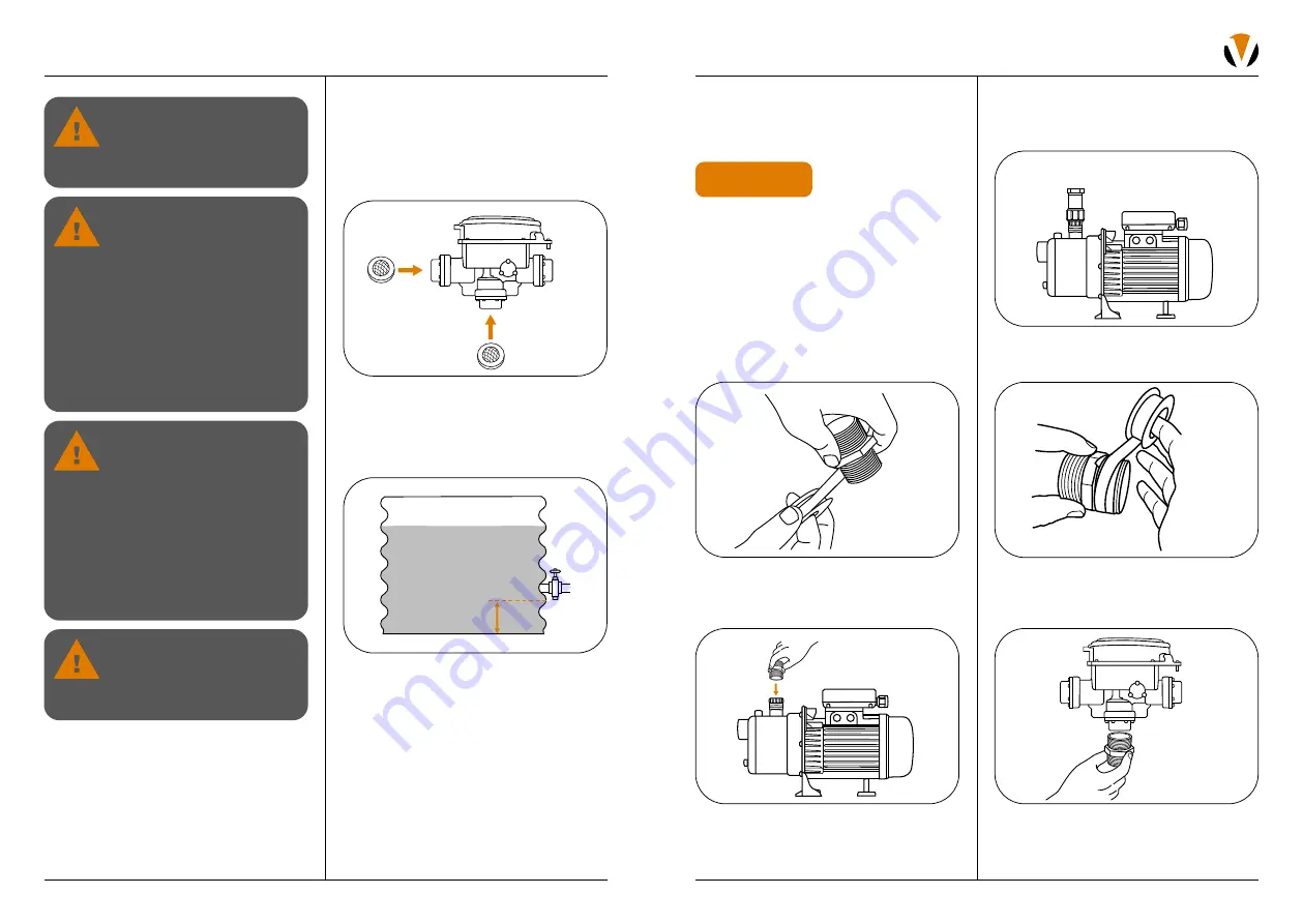
3.  Connect the 25mm female end of the  

barrel union to the nipple until it is 
watertight. Do not overtighten.  

4.  Wrap thread seal tape around another  

25mm nipple.

5.  Thread the nipple into the base of the 

switching unit until it is watertight. Do not 
overtighten.

PART 1: PREPARING  

THE VADA FLOW BOSS 

DIGITAL SWITCHING UNIT

1.  Insert two mesh inline filters on the mains 

water inlet and pump inlet of the unit.

2.  Ensure the height of the tank outlet from 

the base of the tank is at least 100mm. If 
installing a submersible pump, ensure there 
is a 100mm gap between the base of the 
pump and the base of the tank.

Note: 

Clean water is essential for the  

reliable operation of your switching unit.  
It is recommended to install first flush diverters 
and leaf guards on your rainwater tank.

If the incoming mains pressure  
to the property is greater than  
the specified 1000kPa, please  
fit a pressure reduction valve  
of appropriate capacity upstream 
of the Digital Water Switch. 
The recommended pressure is 
500kpa to suit AS/NZS 3500. 
Fitting this type of device to the 
entire house will extend the life of 
other appliances such as washing 
machines, hot water service and 
dishwashers.

This appliance is not intended 
for use by persons (including 
children) with reduced physical, 
sensory or mental capabilities, 
or lack of experience and 
knowledge, unless they have been 
given supervision or instruction 
concerning use of the appliance 
by a person responsible for 
their safety. Children should be 
supervised to ensure that they  
do not play with the appliance.

Brace inlet and outlet connections 
while fitting the Digital Water 
Switch. Any movement of 
connections may disturb internal 
seals and cause leakage.

If the supply cord is damaged 
it must be replaced by the 
manufacturer, its service agent  
or similarly qualified persons in 
order to avoid a hazard.

INSTALLATION

100mm

PART 2: CONNECTING THE 

DIGITAL WATER SWITCHING 

UNIT TO THE PUMP 

In this manual the VFB-DSU is pictured with  
a jet pump. If you’re installing the VFB-DSU 
with a submersible pump, the connection will 
differ slightly. 

If connecting a VFB-DSU to a submersible 
pump, you will need to mount the VFB-DSU 
onto a bracket. 

1.  Wrap thread tape around both ends of  

a 25mm nipple.

2.  Thread the nipple into the female socket  

of the pump discharge until it is watertight. 
Do not overtighten.

HELPFUL HINTS

Summary of Contents for FLOW BOSS VFB-DSU

Page 1: ...DIGITAL WATER SWITCHING UNIT INSTALLATION MANUAL VFB DSU ...

Page 2: ...ce number Product serial number Product model number A smooth day is a good day That s why Vada is dedicated to creating pump solutions that you can count on With a focus on easy selection simple installation and high quality you can hold your head high knowing your reputation is protected It s Vada Performance simplified THANK YOU Scan for set up support ...

Page 3: ...PA 1 bar Max operating pressure 1000kPA 10 bar Minimum flow rate 1 lpm Voltage 1 230 240V 50Hz Maximum electrical load 10A 2400W IP Rating IP44 Vada strongly recommends installing the float switch supplied in the tank on site Installing a float switch prevents air from re entering the suction line and damaging your Vada product Installing a float switch also reduces build up from tank debris enter...

Page 4: ...ion pipe internal diameter must be no smaller than 25mm x2 mesh inline filters Discharge pipe internal diameter must be no smaller than 25mm 16mm hole saw Thread tape Access to a 10A outdoor power point Inline filter AKA Y Strainer Isolation valve Swing check valve Float switch tank If the incoming mains pressure to your property is greater than the specified 1000 kPa 10 bar you MUST fit a pressur...

Page 5: ... type of device to the entire house will extend the life of other appliances such as washing machines hot water service and dishwashers This appliance is not intended for use by persons including children with reduced physical sensory or mental capabilities or lack of experience and knowledge unless they have been given supervision or instruction concerning use of the appliance by a person respons...

Page 6: ...pple from the union Rethread the nipple into the switching unit making sure the union nut remains on the nipple Re join the union to complete connection 6 Connect the VFB DSU to the discharge port on the pump 7 Connect the incoming mains water supply to the MAINS port on the VFB DSU This is marked MAINS with an arrow pointing out of the VFB DSU indicating water flow direction Note Brace this fitti...

Page 7: ...pply by either a Hard wiring Local authorities may require the pump to be hard wired Important If this applies to you the electrical connection must be done by a qualified electrician with pump knowledge according to the National wiring rule AS NZS 3000 and or any local council requirements WARNING Hazardous voltage can cause shock burn or cause death The supply voltage for the Digital Water Switc...

Page 8: ...e This indicates to the switching unit that there is no water in the tank and to switch to mains supply operation 4 Open an outlet on the household side of the VFB DSU The VFB DSU should now be allowing mains water to supply the demand 5 Close the tap and replace the float switch connection If there are any variations to these outcomes please refer to the Troubleshooting section on page 28 70mm ab...

Page 9: ...nstallation will be random 4 To set the date and time press the Time Set button 5 Press either up or down arrow to select the correct day of the month When the correct value is observed press the Time Set button again 9 In the event the user inputs incorrect information the Invalid Data screen will appear 10 The VFB DSU has been set to its basic settings For advanced settings and additional functi...

Page 10: ... which the pump will stop aka cut out 1 Press the RESET button again to select the Cut Out Flow 2 Press the up or down arrow to select the appropriate cut out level Note It is recommended the Cut Out flow rate be 1 lpm Minimum Pressure 1 Press the RESET button until you reach Min Pressure 2 Press the up or down arrow to select the appropriate pressure Note The Min Max pressure required for the swi...

Page 11: ...50Hz Max electrical load 10A 2400W Power standby 3 5W Control power on 30W IP rating IP44 Min flow rate 1lpm Min mains pressure 1 bar Max operating pressure 10 bar Min max water temperature 1 C 40 C Min max ambient temperature 1 C 40 C CONNECTION Mains water supply inlet 25mm FI BSP Pump connection 25mm FI BSP Water outlet connection 25mm FI BSP TECHNICAL INFORMATION C F H I A B J G D E A 52mm B 1...

Page 12: ...ystem will automatically default to mains water supply When power is restored the switching unit will revert to normal operation Loss of Mains Supply Water If town supply water is shut off in your area the switching unit may not be able to detect water demand in the household e g if the toilet cistern needs refilling You can override normal control and start the pump to supply water out of the rai...

Page 13: ...lly connected Ensure that it is isolated from electrical supply during installation and any subsequent service work Unit should only be serviced by qualified personnel or licensed service agent OFF 6 If rainwater is detected the system will revert to normal operation 7 If no rainwater is detected then the switching unit will go to a further 7 day lock out as per step 4 The unit will continue to au...

Page 14: ...k maximum run time setting OVER CURRENT Error Code 3 Over current detected measured current exceeds 10amps 1 Check pump for mechanical resistance Refer to troubleshooting in pump manual 2 Check pump motor for electrical faults Refer to troubleshooting in pump manual NO PUMP CONNECTED CHECK FUSE Error Code 4 No load detected 1 Check to make sure the pump is connected 2 Check for blown fuse on the b...

Page 15: ...ater 3 Remove pump barrel union 4 Inspect clean replace filter Pump is not primed 1 Open gate valve and prime the pump Refer to pump manual on how to prime the pump 2 Reset the switching unit by pressing Reset key SYMPTOM CAUSE SOLUTION Pump continually runs or cycles on and off consistently over time when no outlets open Leak in the plumbing system 1 Identify where the leak is e g toilet or tap l...

Page 16: ...atives or an authorised customer service workshop and any attempt to repair the device by the customer or unauthorised third parties shall terminate the warranty WARRANTY CONDITIONS The warranty will apply only under all the following conditions The pump has been installed by a qualified licensed personnel The pump is returned in good condition and has not arrived damaged The pump is located so th...

Page 17: ......

Reviews: