13
12
VADA FLOW BOSS
DIGITAL WATER SWITCHING UNIT
VFB-DSU
INSTALLATION MANUAL
b. Inserting the plug into the
suitable socket outlet:
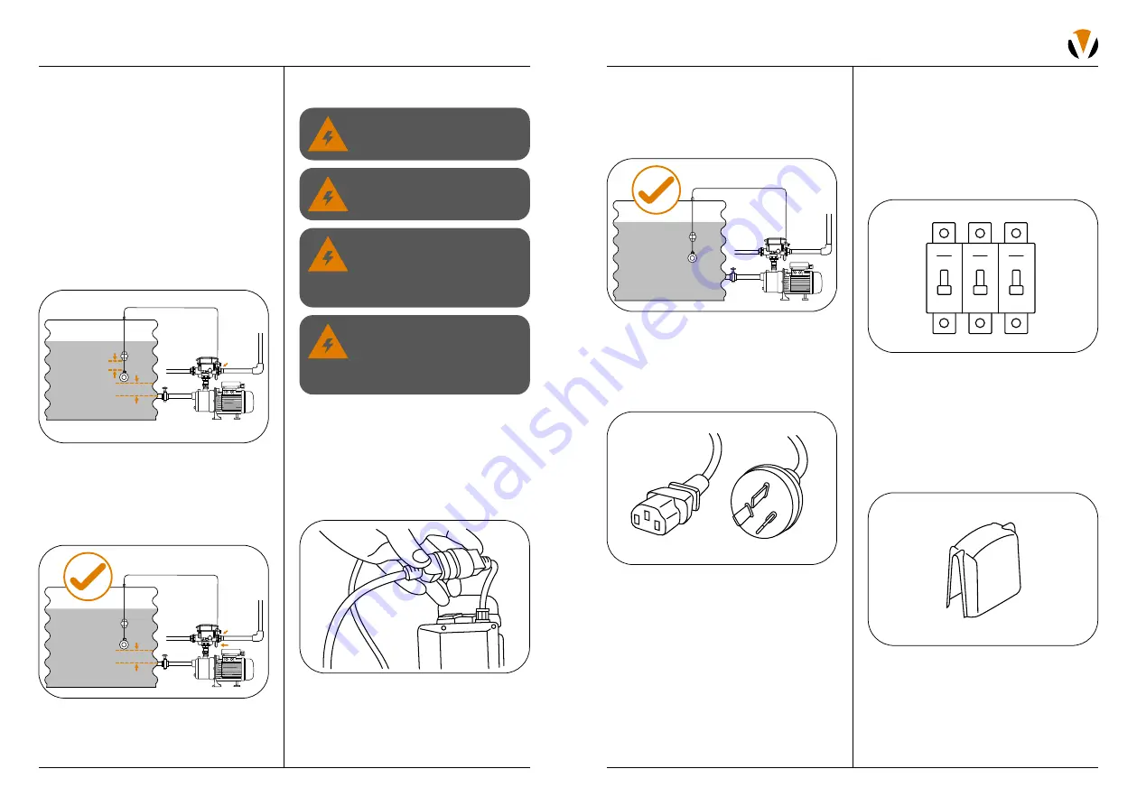
It is recommended to connect the
switching unit to a socket outlet
protected by a residual current device
– RCD (also known as an earth leakage
circuit breaker – ELCB) with a rated
tripping current not exceeding 30mA.
Note:
Contact a qualified electrician if you
cannot verify that the socket outlet is protected
by RCD. RCD tripping indicates an electrical
problem. If the RCD trips and will not reset,
have a qualified electrician inspect and repair
the electrical system.
4. Protect your pump solution from wind, rain
and sun with a suitable pump cover.
Congratulations, the
installation is complete!
INSTALLATION
ELECTRICAL CONNECTION
1. Before connecting the unit to an electrical
power supply, connect the pump and
switching unit using the provided IEC
appliance connectors on the end of the
interconnection cords. Ensure there are no
water traces on the connectors. Push them
firmly into each other to ensure intended
splash (water) proof protection.
2. Check that the tank level sensor is securely
connected to the base of the unit using the
bayonet fitting, and the lead is cable tied
to the connecting pipework to stop it from
being pulled free.
3. Connect the switching unit to the power
supply by either:
a. Hard wiring:
Local authorities may require the pump
to be hard wired.
Important:
If this applies to you, the electrical
connection must be done by a qualified
electrician with pump knowledge according
to the National wiring rule (AS/NZS 3000) and/
or any local council requirements.
WARNING: Hazardous
voltage can cause shock,
burn, or cause death.
The supply voltage for the
Digital Water Switch must be
within 230–240V.
If the power supply cord or
pump interconnection cord is
damaged, it MUST be replaced
by an authorised service agent
to avoid hazard.
To avoid dangerous or fatal
electrical shock, turn off power
to the digital water switch
before working on any electrical
connections.
3. Insert the float into the tank:
Surface tank installations:
Drape the level sensor up against the
side of the tank, lifting the cable until the
float is 70mm above the suction. Mark the
positions of the cable that is level with the
roof of the tank using marking tape (not
supplied).
In-ground installations:
Lower the float into the tank. Position the
float 70mm above the suction fittings or
pump inlet. Use marking tape on the cable
to indicate top of tank position.
4. Once in position, route the cable to the
switching unit and plug the connector to
the matching receptor on the underside
of the VFB-DSU. Using cable ties, fix the
cable to the pipework near the switching
unit to avoid the cable being pulled free.
70mm above suction
Note:
Do not adjust
factory setting
Cable tie
70mm above suction
Mains
Household
Cable tie
Summary of Contents for FLOW BOSS VFB-DSU
Page 1: ...DIGITAL WATER SWITCHING UNIT INSTALLATION MANUAL VFB DSU ...
Page 17: ......


