24
VADA FLOW BOSS
HORIZONTAL MULTISTAGE PUMP
VFB-HM110
INSTALLATION MANUAL
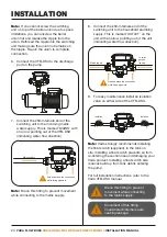
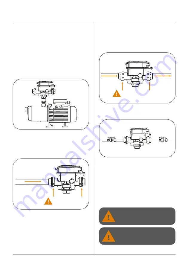
8. Connect the 25mm female end of the
switching unit to the household plumbing
supply. This is marked ‘OUTLET’ on the
unit with an arrow pointing out of the unit
(indicating water flow direction).
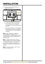
9. For easy maintenance install an isolation
valve on either side of the VFB-DSU.
Note:
Vada strongly recommends installing
the float switch (supplied), in the tank on
site. Installing a float switch prevents air from
re-entering the suction line and damaging your
Vada product. Installing a float switch also
reduces build up from tank debris entering
the pump.
For full installation instructions, refer to the
Vada VFB-DSU manual.
Note:
If you cannot screw the switching
unit on top of the barrel union due to space
limitations, you can unscrew the barrel
union nut and release the nipple from the
union. Rethread the nipple into the switching
unit making sure the union nut remains on
the nipple. Re-join the union to complete
connection.
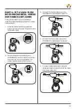
6. Connect the VFB-DSU to the discharge
port on the pump.
7. Connect the 25mm female end of the
switching unit to the incoming mains
water supply. This is marked ‘MAINS’ with
an arrow pointing out of the VFB-DSU
(indicating water flow direction).
Note:
Brace this fitting to prevent movement
while connecting to the mains supply.
To toilet,
garden,
laundry
Mains supply
Grip and brace the connection
while fitting pipework
Brace this fitting to prevent
movement while connecting
to the mains supply.
Movement of this fitting
could disturb internal seals,
causing leakage.
INSTALLATION
Grip and brace the connection
while fitting pipework
Mains supply
Isolation
valve
Isolation
valve
Summary of Contents for VFB-HM110
Page 1: ...HORIZONTAL MULTISTAGE PUMP INSTALLATION MANUAL VFB HM110...
Page 53: ...53...
Page 56: ......


