Squiggle Video Whiteboard Kit
Squiggle Manual 342-0172 Rev. B
Page 6 of 16
Installation Step by Step:
Before Installing:
•
Keep other IR or ultrasonic devices and reflective surfaces away from the whiteboard location.
•
Since Squiggle is being installed next to an existing whiteboard, pull out the tape measure and prepare to
measure precise positions for the location of the EZTub and Digital Control Panel. Typically, the Squiggle
Quick-Connect Interface is located at the head-end, so we’ll make that assumption here too.
Step 1:
Measure the existing whiteboard. Squiggle is always
mounted on the left side and center of the whiteboard.
The center of the Digital Control Panel, not the EZTub,
must be centered on the left side of the white board.
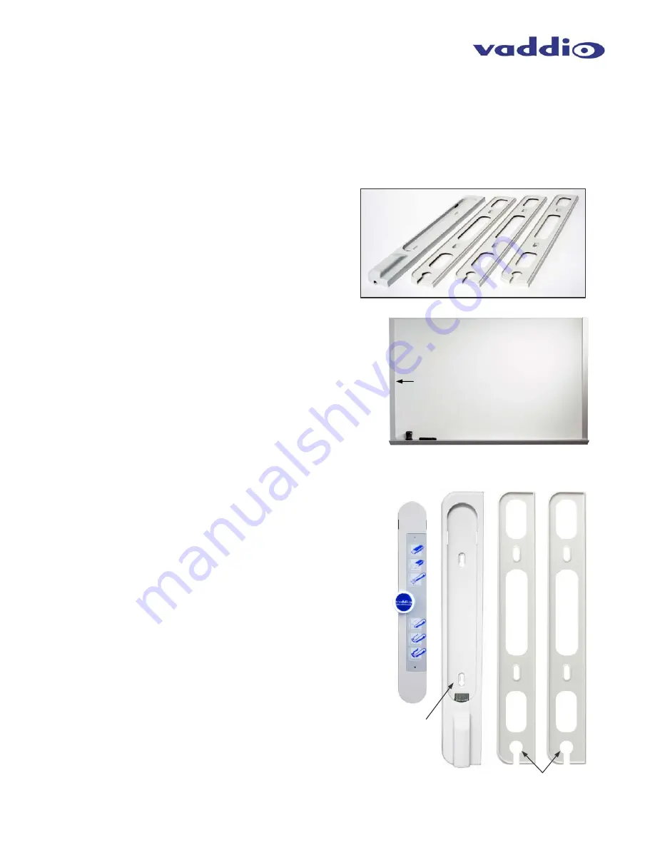
The system is shipped with the EZTub and three (3) ¼”
thick wall spacers (right) to allow the EZTub and Digital
Control Panel to sit flush with the whiteboard surface.
In our mounting example, the whiteboard is a 3’ x 5’
and sits about 1” out from the wall. Make a mark at 1.5’
on the left side of the whiteboard surface and this will
be where the center blue IR receiver (with the Vaddio
Logo) will be aligned.
Step 2:
Determine the required number of wall spacers to raise the
EZTub and Digital Control Panel to the correct height to be even
with the surface of the whiteboard. In this example, the two ¼”
spacers and the EZTub will provide the 1” height needed.
Step 3:
Stack the EZTub and two (2) spacers. Hold them to the left side
of the whiteboard and center the opening for the Digital Control
Panel on the mark that was made on the whiteboard. Snap in
the Digital Control Panel and adjust the height so the center blue
dot is on the center mark. Using the removal tool, remove the
Digital Control Panel and mark the position of the screws. The
EZTub has two keyhole slots and the spacers have oval slotted
screw holes. While still holding the EZTub and Spacers against
the left side of the whiteboard, make two marks on the wall at the
top of the keyhole slots on the EZTub.
Step 4:
Install the two (2) provided spiral wall anchors, or installer’s
preferred anchors at these marks.
Step 5:
Route the Cat-5e cable from the Squiggle Quick-Connect
Interface and decide if the cabling will run inside the wall behind
the EZTub or will be surface mounted. Each Wall Spacer (see
illustration on right) has a cable pass-thru at the bottom to allow
the Cat-5e cable to pass through the wall to the RJ-45 connector
on the back of the EZTub connector.
Center, Left Side of Whiteboard
Digital Control Panel, EZTub and two (2) Wall Spacers
(left to right below)
Cable pass-thru into
wall behind EZTub
Keyhole
Slot
EZTub and three (3) all Spacers
Any Whiteboard


