BaseSTATION
Vaddio BaseSTATION - Document Number 342-0756 Rev A
Page 10 of 40
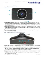
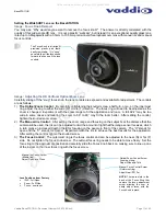
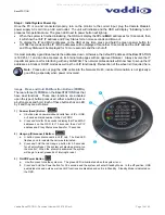
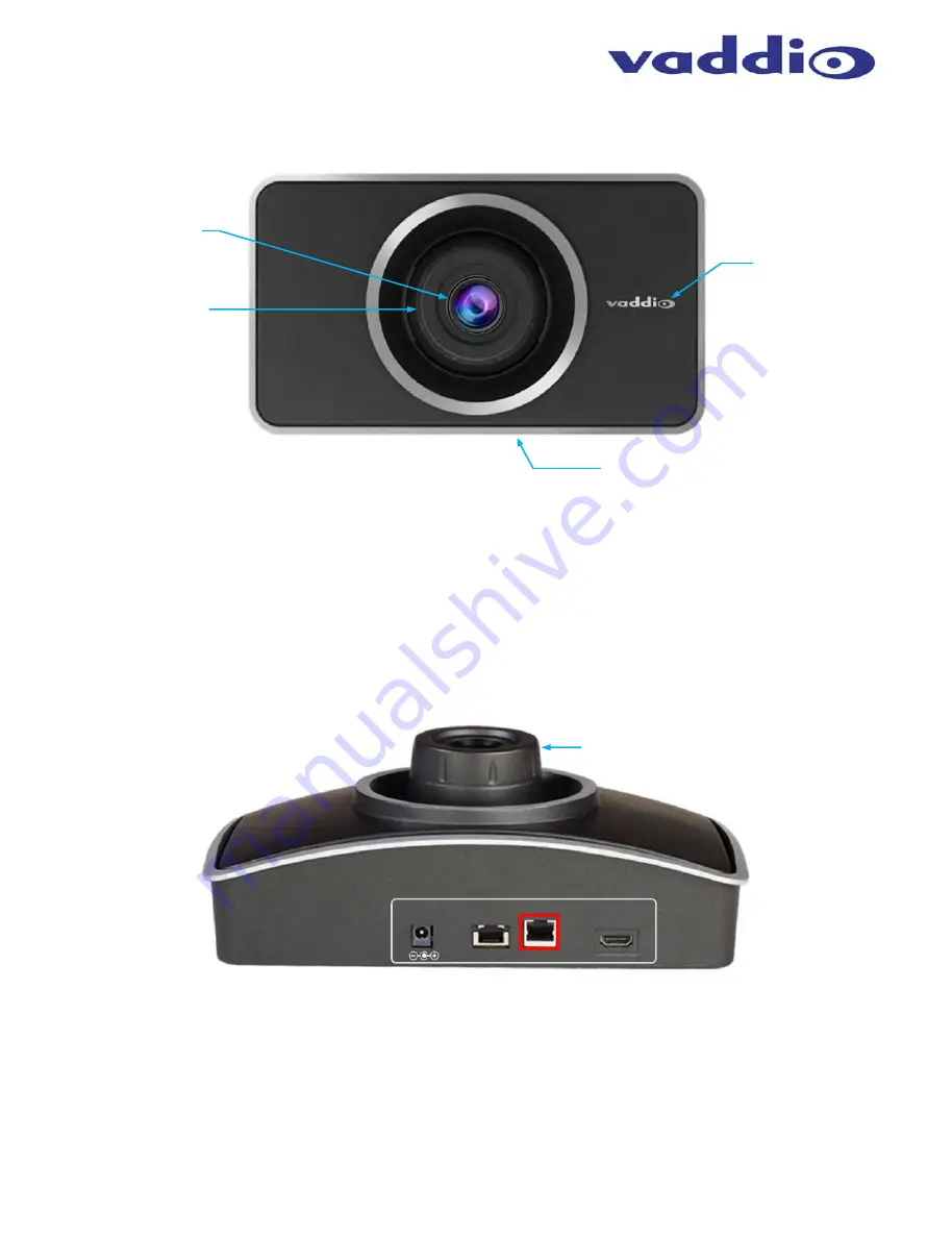
Anatomy of the BaseSTATION Camera Module
Image: BaseSTATION HD Camera Module
1) Camera Module and Lens:
Based on the WideSHOT
HD camera with manual, real glass 3mm-10.5mm
varifocal (3X) optical zoom lens producing 82.2° horizontal field of view on the wide end and 27.4° on the tele
end in a 16:9 format. This camera has no digital zoom to smear up the image and make the pixels huge and
fuzzy. Furthermore if somebody really wanted a diagonal specification, it would be 94.31°, which is not a valid
camera specification anyway.
2) Focus Knob and Adjustments:
The HD lens has manual focus, manual iris and manual zoom. The Focus
Knob of the camera slips off for access to the iris and controls. The camera can be adjusted 30° down, 10° up
and 5° to either side (left or right)
3) Connection
Panel:
Located on the bottom of the Camera Module. Connections are detailed below.
4) Really Cool Logo (RCL):
The RCL is in the Vaddio benchmark silver and is tastefully placed to the right side
of the Camera Module front panel.
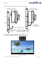
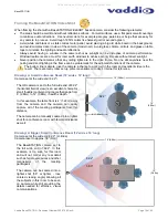
Image: Connector Panel of the BaseSTATION Camera Module
1) Power Jack:
5.5mm x 2.5mm coaxial power jack (positive center): Use only the provided 24 VDC, 3.0 Amp switching
power supply. Provides power to the Camera Module and the BaseSTATION Dock.
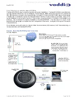
2) Network
Jack:
Ethernet 10/100 jack with Green and Yellow LEDs verifying connection and activity. The BaseSTATION
has two IP addresses; one address is dedicated to the VoIP User Agent and the second IP address is for the embedded
web server. The Ethernet connection also provides a second port at the BaseSTATION Dock for connection to the PC.
A
third IP address is also required for the PC that runs the UC application software.
3) LINK
Connector:
Proprietary high speed digital link between Dock and Camera Module uses a 25’ Cat-6 SSTP cable
with individually shielded pairs (included) to connect the LINK ports. The LINK port is marked in red on both sides
.
4) HDMI Connector:
HDMI output for connection to the room’s display extending the connected PC’s display and far-end
audio from the UC application. The HDMI digital audio/video output is routed to the room monitor and uses the speakers
built-in to the room monitor for sound.
➊
➋
➌
➍
24 VDC
3.0 A, LPS
Focus Knob
NETWORK
LINK
HDMI OUT
➊
➋ ➌
➍
All manuals and user guides at all-guides.com


