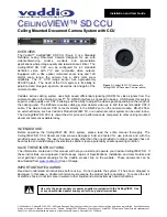
CeilingVIEW SD CCU
Vaddio CeilingVIEW SD CCU Installation and User Guide - Document 341-769 Rev. A
Page 2 of 16
UNPACKAGING – SYSTEM COMPONENT LISTS
Carefully remove all parts from the packaging and identify the following parts:
CeilingVIEW SD, Part Number 999-2009-000 (NTSC) includes:
•
One (1) CeilingVIEW SD Camera Enclosure
•
One (1) CeilingVIEW Camera Control Unit
•
One (1) White Trim Ring with two (2) white screws
•
One (1) Vaddio IR Remote Controller
•
One (1) Quick-Connect CV HD/SD Interface
•
One (1) PowerRite 36VDC, 2.78A Power Supply (for Quick-Connect CCU)
•
One (1) PowerRite 24VDC, 2A Power Supply (for Quick-Connect CV HD/SD)
•
One (1) 2-position Phoenix Type Connector (Tally port on CCU)
•
Two (2) Adjustable ceiling tile support rails with two (2) knurled knobs
•
One (1) RJ-45 to DB9 EZCamera Control Adapter (998-1001-232)
•
One (1) AC Cord Set for North America
•
Installation and User Guide (341-769)
CeilingVIEW SD, Part Number 999-2009-001 (PAL) includes:
•
One (1) CeilingVIEW SD Camera Enclosure
•
One (1) CeilingVIEW Camera Control Unit
•
One (1) White Trim Ring with two (2) white screws
•
One (1) Vaddio IR Remote Controller
•
One (1) Quick-Connect CV HD/SD Interface
•
One (1) PowerRite 36VDC, 2.78A Power Supply (for Quick-Connect CCU)
•
One (1) PowerRite 24VDC, 2A Power Supply (for Quick-Connect CV HD/SD)
•
One (1) 2-position Phoenix Type Connector (Tally port on CCU)
•
Two (2) Adjustable ceiling tile support rails with two (2) knurled knobs
•
One (1) RJ-45 to DB9 EZCamera Control Adapter (998-1001-232)
•
One (1) Euro AC Cord
•
One (1) UK AC cord Set
•
Installation and User Guide (341-769)
INSTALLATION INSTRUCTIONS:
The CeilingVIEW SD CCU Document Camera is an integrated document/object camera specifically designed
for installation in a suspended ceiling tile above a conference table, lectern or work surface. Recommended
ceiling height range is between 8’ and 12’ (2.44m to 3.66m).
Before Starting the Installation
•
IMPORTANT NOTE: Please review Figure 5 closely. The Quick-Connect CCU for the CeilingVIEW
document cameras utilizes only the ports shown in the figure. All Power for the Camera Module, as
well as video returned from the Camera Module is delivered via the Quick-Connect CV HD/SD, also
shown in the picture.
•
Before starting the installation of the CeilingVIEW SD CCU Document Camera, check above the
ceiling where you plan to install the camera and make sure the area is clear of obstructions and
confirm that there is adequate room for the camera enclosure.
•
When terminating your CAT-5 cabling, make sure that you test each cable for proper termination of
all ends with a CAT-5 continuity tester.
•
All above-ceiling work must conform to local building codes and should be performed by qualified
personnel.
•
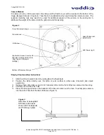
The camera module enclosure and tile support rails allow for superior flexibility and positioning
freedom when used with 2’x2’ and 2’x4’ ceiling tiles. The camera does not have to be mounted in
the center of the tile.
•
For cutting ease, remove the ceiling tile and place on a suitable and safe work surface.
•
Because the Quick-Connect CCU is an in-line device, the CeilingVIEW SD CCU camera system is
not compatible with daisy-chain configurations. You must have a dedicated RS-232 control port
connected to the Quick-Connect CCU.

