IN-Ceiling Half-Recessed Enclosure for HD Series and RoboSHOT Cameras
IN-Ceiling Half-Recessed Enclosure Manual
●
Document Number 342-0177 Rev. E
Page 5 of 8
Step 2:
Remove the ceiling tile from the grid. Place the tile on a safe work surface away from finished furniture.
Use the supplied Tile Support Brace as a template and trace out the round opening for the camera bezel. Measure
twice, cut once. Carefully cut this hole in the ceiling tile, scoring the front of the tile first with a sharp utility knife.
Step 3:
After carefully cutting the tile, replace the tile in the grid. From one tile over, put the one-piece tile brace in
place on the cut tile and line up the circular holes. Tie the tile support brace up to the structure now (or wait until
later). Use the hanger holes along either side of the tile support brace. The assembly with camera will be close to
10lbs. (22kg) and it is important to support that weight with the building structure rather than just the ceiling grid.
Step 4: Using the Quick-Connect SR, Quick-Connect DVI/HDMI-SR, Quick-Connect USB or Quick-Connect
USB Mini Interfaces and the HD-Series or RoboSHOT Cameras:
Two (2) Cat-5e cables are required for the
cameras to operate with either the Quick-Connect SR Interface or the Quick-Connect DVI/HDMI SR Interface.
Route, test and mark the Cat-5e cables
EZ-Power/Video
and
RS-232/IR
(these cables can be up to 100’ /30.48m
in length).
If using the Quick-Connect Universal CCU and the HD Series or RoboSHOT Cameras:
Three (3)
Cat-5e cables are required.
Route, test and mark the Cat-5e cables
Power
,
Video
and
RS-232
(these cables can
be up to 500’/152.4m in length). The EZIM CCU Slot Card is required for the CCU System for the HD Series
cameras and is packed out with the WallVIEW CCU systems. The Power and Video RJ-45 connectors are on the
Slot Card. When using the CCU, the IR receiver and emitter board is bypassed altogether.
Step 5:
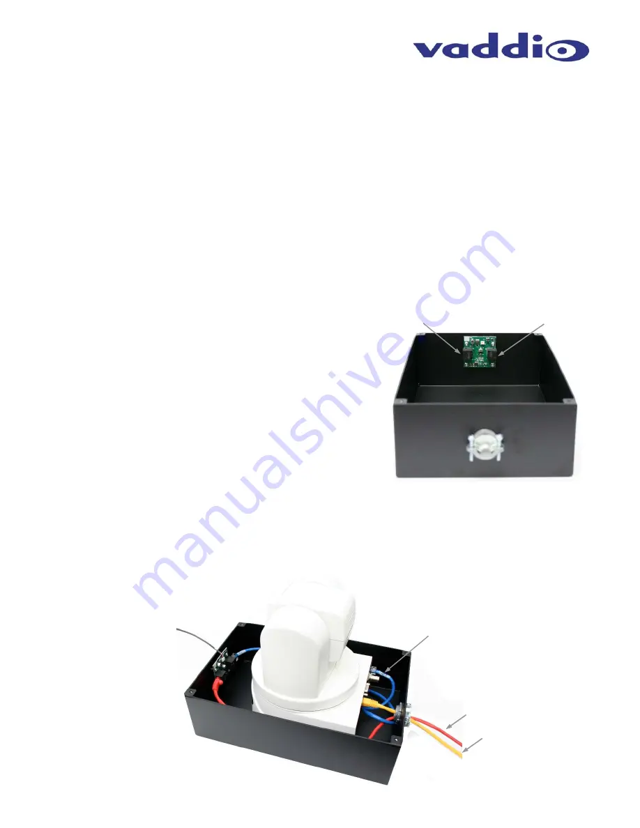
Take the back box and attach the conduit connector.
Loosen the connector enough to pass through the RJ-45
connectors. On the front of the back box, there is an IR
emitter/Power circuit board which allows the camera to be
controlled via IR Remote from the outside of the back box with the
IR Receiver in the trim Ring. This circuit is for use with the Quick-
Connect SR Interface or the Quick-Connect DVI/HDMI Interface.
The RJ-45F on the Left is the
Power/Video IN
and the RJ-45F on
the right is the
Power/Video OUT
and goes to the
EZ-Power
Video
RJ-45F on the Back of the HD or RoboSHOT cameras.
These connectors will be clearly marked.
Step 6:
Holding the camera by the base, use the supplied ¼”-20 screws and secure the camera to the back box. Connect
the Power/Video Cat-5e to the IR emitter/Power board
Power/Video IN
RJ-45 (Power/Video Cable is red). Connect
the supplied 24” (609.6mm) Cat-5e patch cable from the
Power/Video OUT
on the IR emitter/Power board to the
EZ-Power Video RJ-45 connector on the back of the HD or RoboSHOT cameras (this cable is blue). The RS-232
cable is connected to the RS-232/IR OUT jack on the back of the camera and is routed back to the controller or the
Quick-Connect Interface. Connect the 18” (457.2mm) 3-conductor IR cable to the circuit board as shown below.
The other end of this cable will be connected to the IR Receiver board on the Trim Ring.
POWER/VIDEO IN
FROM Quick-Connect
POWER/VIDEO OUT
TO CAMERA
Conduit
Connector
IR Cable to Trim Ring.
Attach to connector at
top of the Circuit Board
Power/Video Cable (to IR Board)
RS-232 Cable
If using the IR remote only to
control the camera, this
cable is not required.
24” Internal Power/Video
Cable (from IR Board to
EZPOWER/VIDEO RJ-45)
HD-19AW
White PTZ
Camera
Note:
See next page if using an
HD-20/22/30/USB Camera.
A platform spacer block is
required.
Wiring for use with the Quick-Connect: SR
DVI/HDMI-SR, USB or USB Mini Interfaces


