TrackVIEW Install Guide 341-337 Rev. E
Page 13 of 32
TrackVIEW and Peripherals Install Guide
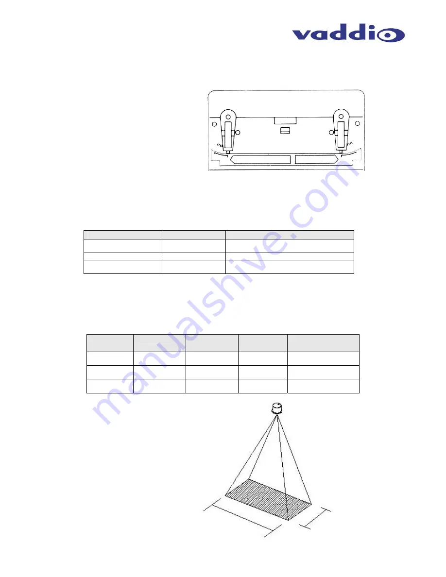
Each Active IR Zone is essentially a rectangular area that is narrow at the top and wider at the bottom. To
adjust the IR zones A (Approach) and B (Inner) zone depth, use the mechanical focusing elements on the side
of the sensor and set them to tailor the depth of both sensing zones
On the Opposite side of the IR sensor from the Approach and Inner area adjustment potentiometers, there are
three other controls to be set (Table 3). Set these parameters to the appropriate value.
Control
Value Range
Recommended Setting
Frequency Switch
L to H
Change the frequency switch when the diction
area of another IR sensor is overlapping.
Presence Detection Timer
2 – 15 – 60 Seconds
Set to 60 Seconds for this application
Mounting Height Setting
6.5’ (2m) to 13.1’
(4m)
Adjust to height of ceiling height of IR Sensor
installation
Like any IR sensor, the ceiling height will affect the overall IR zone size. Table 4 below lists three common
ceiling heights and the variable zone sizes available at those heights.
Ceiling
Height
Width (D)
Depth (A)
Approach
Depth (B)
Inner
Total Depth (C)
(A + B)
8.2’ (2.5m)
71” (180cm)
0” – 51”
(0 – 130cm)
0” – 31”
(0 – 80cm)
0” – 82”
(0 – 208cm)
9.8’ (3m)
86” (218cm)
0” – 59”
(0 – 150cm)
0” – 39”
(0 – 100cm)
0” – 98”
(0 – 249cm)
13.1’ (4m)
114” (290 cm)
0” – 74”
(0 – 190cm)
0” – 51”
(0 – 130cm)
0” – 125”
(0 – 317cm)
Approach Area
Inner Area
26°
18°
0°
0°
Figure 15:
Adjust the focusing elements for both
the A (Approach) and B (Inner) zone
depth.
Table 4:
Ceiling Heights and sensing zone sizes (see Figure 15 for zone labeling)
Figure 16:
Example
In an 9’ (2.74m) ceiling and the ceiling
height set accordingly, the width of the
rectangular sensing zone will be
approximately 78” (1.98m) and the
rectangle depth can range between 0”
(0m) and 89” (2.26m).
78”
1.98m
Variable
0 – 89”
(0 – 2.26m)
Table 3:
Control adjustments for tailoring IR Sensor response


