WallVIEW CCU HD-18 HD-SDI
WallVIEW CCU HD-18 HD-SDI Manual 341-988 Rev. A
Page 4 of 26
The Components (continued)
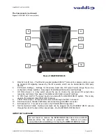
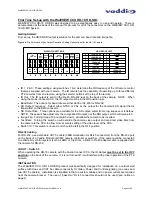
Figure 3:
WallVIEW HD-18 camera (back)
5.
RS-232 In & IR Out – The RS-232 accepts modified VISCA™ protocol for camera control, as well
as transmits IR signaling received by the IR receivers, which can be transmitted to third party
devices.
6.
DIP Switch Settings – Settings for IR remote, baud rate, SD output format, image flip can be
configured on these switches. See page 6 for additional information switch settings.
7.
HD Video Select - A rotary switch allows the user to choose the component HD output video
resolution and format. See page 6 for additional information on switch settings.
8.
12 VDC Input - NOTE: The power input is not used with the WallVIEW HD-18 system. This is only
used on the standard, ClearVIEW HD-18 camera.
9.
YPbPr Video Output - Component HD video is fed through the DB-15 connector.
10.
SD Video Output - Standard definition video is fed through the BNC connector.
11.
EZ Camera Port - This port is not used in the CCU/HD-SDI Configuration
12.
Slot for Optional Cards - Optional slot cards can be plugged into the WallVIEW HD-18 camera
through the slot in the back of the camera base…like the EZIM HD-SDI Slot Card.
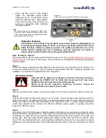
IMPORTANT SAFEGARD
Rear of WallVIEW HD-18
5
6
7
8
9
10
11
12
Do not insert or remove the EZIM HD-SDI Slot Card into an HD-18
Camera when the camera is powered ON. Detach all power
connectors before installing or removing the EZIM HD-SDI Slot Card.


