Assembly instructions
26
Ver.07/06/01 07/06/01
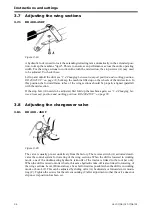
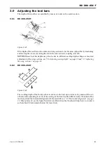
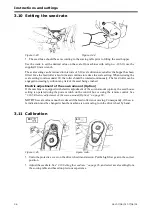
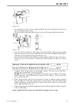
2.16 Fitting the pre-emergence bout marker, mfg. no. 10 310-
Place the seed drill unfolded on a firm surface and hitched to a tractor. Raise or lower the seed drill
to bring the seed coulters about a centimetre or so above the ground. Then select the floating position
or switch off the tractor and release the hydraulic pressure so that the seed drill sinks to the ground.
Stop the tractor, turn off the engine and switch off the control box. Do not stand on the wheels when
fitting the pre-emergence bout markers, since they may rotate.
2.16.1 Installing the pre-emergence bout marker for centre tramlining (standard)
and side tramlining on RD 400 F
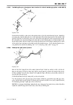
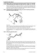
Figure 2.22
Install the front part of the frame (B) in the centre of the middle wheel beam of the drill. The mounting
bolts (C) and the frame should be fitted from the left side against two of the fixing eyelets.
Connect the light connectors (K) in the frame joints and assemble the frame parts.
Adjust the space (D) to the correct tramline spacing. Verify that this tramline spacing matches the
selected tramlining (see ”3.17.1 Adjusting track width” on page 64) and make sure the lateral position
is correct.
2.16.2 Fitting the hydraulic system
Figure 2.23
Remove the three plugs (E) from the outlets marked 8 and 9 at the top and rear of the valve block.
Remove the plugs with care as there may still be some hydraulic pressure remaining in the circuit. Fit
the cartridge valve (F), the solenoid (G), hydraulic hoses (H), hose connections and ram (I). See also
the spare parts list.
Fit the Hirschman switch (J) marked 20 on the solenoid (G).
Test the operation of the pre-emergence bout marker. When the seed drill is raised the pre-emergence
bout marker should always be lifted and when the seed drill is lowered it should lowered for tramli-
ning (Lamps 5 lights up on the control box).
NOTE!
If you step past tramlining manually the pre-emergence bout marker may sink without the hy-
draulic control being used. In such case, raise the seed drill again!
B
C
C
D
K
Summary of Contents for RAPID RD F Series
Page 1: ...Ver 1 3 07 06 01 900107 en Instructions Seed drill RAPID series RD 300 450 F No 10 026 11 999...
Page 2: ...2 Ver 1 3 07 06 01...
Page 6: ...6 Ver 1 3 07 06 01...
Page 16: ...Assembly instructions 16 Ver 07 06 01 07 06 01...
Page 23: ...RD 300 450 F Ver 1 3 07 06 01 23...
Page 41: ...RD 300 450 F Ver 1 3 07 06 01 41...
Page 47: ...RD 300 450 F Ver 1 3 07 06 01 47...
Page 108: ...Appendices 108 Ver 07 06 01 07 06 01 7 4 Electrical diagram Figure 7 8 307335...

