Instructions and settings
44
Ver.07/06/01 07/06/01
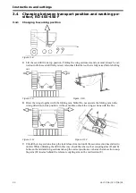
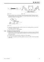
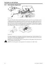
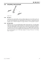
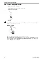
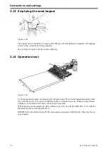
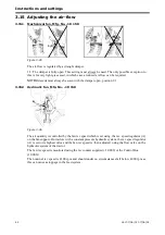
3.15.4 Hydraulic fan "Fenix", manufacturing no. 10 260-
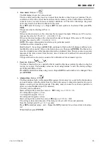
The air volume is adjusted using the fan speed.
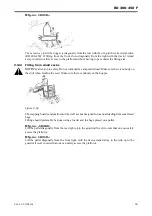
The fan speed can be adjusted in various ways, depending on the tractor on which it is mounted:
A
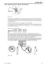
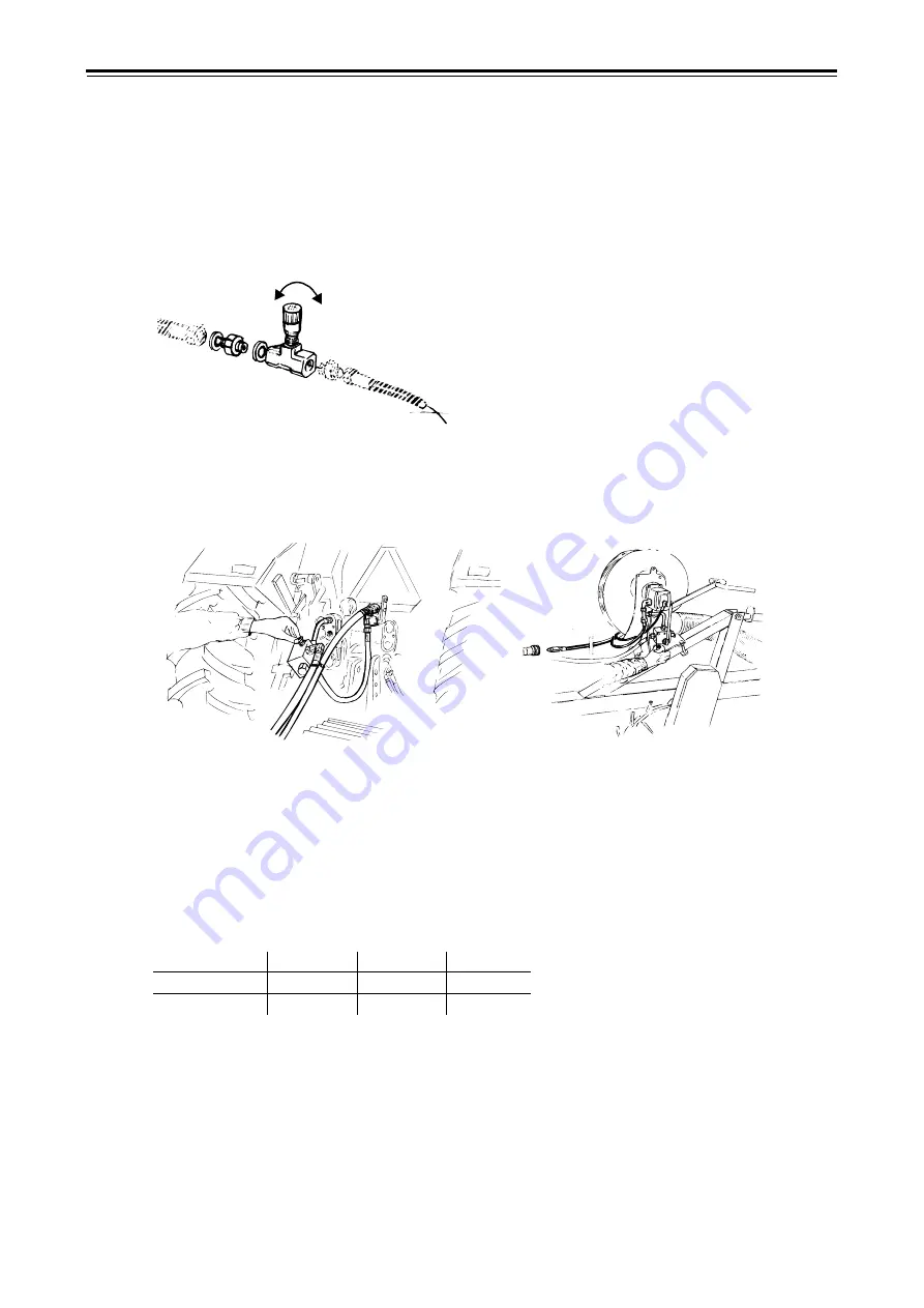
The fan is controlled using the tractor’s flow valve. A flow valve is available on most tractors
with a constant pressure hydraulic system. If the tractor has a priority hydaulic connector, be
sure to use this. Control of the hydraulic pressure from the tractor’s hydraulic system will then
be optimized for the hydraulic fan and on the tractor. Before installing an external valve accor-
ding to alternative (b) or (c), check whether a flow valve is optionally available for the tractor’s
hydraulic system.
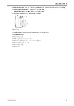
Figure 3.39
B
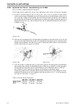
If the tractor is equipped with a constant pressure hydraulic system but no flow valve, the fan
speed is instead controlled with a check valve installed on the pressure line between the tractor
and the sowing machine. The check valve can be ordered as already fitted or can be fitted on
models without this valve (part no. 420160).
C
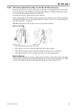
If the tractor has a constant pressure system, the fan rpm can be adjusted using an additional
rpm regulator placed between the hydraulic hoses of the tractor and drill or on the fan holder.
The optional speed regulator can be ordered fitted or can be fitted later (part no. 420154).
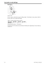
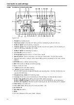
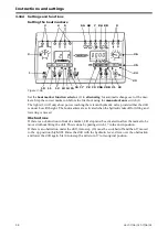
Press button 18 on the control box to display the fan speed on the display again.
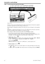
The fan speed alarm of the control box has been preset at the factory to min. 3800 rpm and max.
4800 rpm. The alarm levels can be adjusted from the control box. See ”3.16.3 Programming
the Type III Control Box” on page 54.
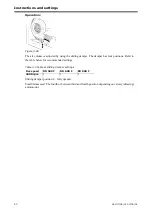
Figure 3.40
Figure 3.41
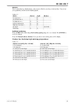
Table 3.2 Recommended fan speed
RD 300 F
RD 400 F
RD 450 F
Small seeds
2200 rpm
2200 rpm
2200 rpm
Corn
3500 rpm
4100 rpm
4300 rpm
-
+
Summary of Contents for RAPID RD F Series
Page 1: ...Ver 1 3 07 06 01 900107 en Instructions Seed drill RAPID series RD 300 450 F No 10 026 11 999...
Page 2: ...2 Ver 1 3 07 06 01...
Page 6: ...6 Ver 1 3 07 06 01...
Page 16: ...Assembly instructions 16 Ver 07 06 01 07 06 01...
Page 23: ...RD 300 450 F Ver 1 3 07 06 01 23...
Page 41: ...RD 300 450 F Ver 1 3 07 06 01 41...
Page 47: ...RD 300 450 F Ver 1 3 07 06 01 47...
Page 108: ...Appendices 108 Ver 07 06 01 07 06 01 7 4 Electrical diagram Figure 7 8 307335...

