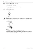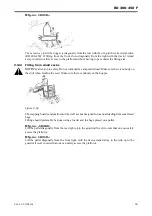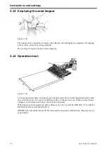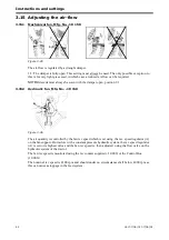
Instructions and settings
52
Ver.07/06/01 07/06/01
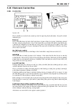
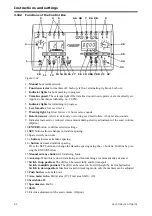
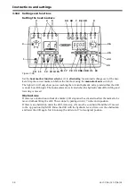
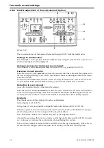
3.16.2 Functions of the Control Box
Figure 3.52
1 Manual bout marker switch
2 Function selector for markers off, both up, left out, alternating, right out, both out.
3 Indicator lights for bout marking in progress
4 Tramline guard. These lamps light if the tramline doors do not operate or are incorrectly set.
Applies to machines with mftg. no. 10 950-.
5 Indicator lights for tramlining in progress.
6 Level monitor, low seed level.
7 Warning light, high/low fan revs. A buzzer also sounds.
8 Rotation sensor. Alerts to stationary or slowing seed feed rollers. A buzzer also sounds.
9 Indicates increased or reduced sown amount during electric adjustment of the seed volume.
(Option)
10 ENTER button, confirms selected settings.
11 SET button, allows changes to tramline spacing.
12 Spare switch, not in use.
13 + button, increases tramline spacing.
14 - button, decreases tramline spacing.
Press the SET button and change the tramline spacing using the +/- buttons. Confirm by pres-
sing the ENTER button.
15 Manual advance button for tramlining bouts
16 Autostep. When this is down, tramlining and bout marking are automatically advanced.
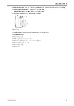
17 Switch in up position: The drill can be raised fully and for transport
Switch in middle position: The drill can be raised to Low lift height by tractor hydraulics
Switch in down position: Machine locked in working mode, only the markers can be adjusted
18 Push button, current fan revs.
19 Area meter in ha. Partial area (19), Total area Shift + (19).
20 Seed shut-off.
21 Speedometer, km/hr
22 Shift.
23 Electric adjustment of the seed volume. (Option)
3
4
5
6A 6B
7 8A 8B
9
26
25
24
10
11
12 13 14 15 16 17 18 19 20A 20B 21 22
23
2
1
Summary of Contents for RAPID RD F Series
Page 1: ...Ver 1 3 07 06 01 900107 en Instructions Seed drill RAPID series RD 300 450 F No 10 026 11 999...
Page 2: ...2 Ver 1 3 07 06 01...
Page 6: ...6 Ver 1 3 07 06 01...
Page 16: ...Assembly instructions 16 Ver 07 06 01 07 06 01...
Page 23: ...RD 300 450 F Ver 1 3 07 06 01 23...
Page 41: ...RD 300 450 F Ver 1 3 07 06 01 41...
Page 47: ...RD 300 450 F Ver 1 3 07 06 01 47...
Page 108: ...Appendices 108 Ver 07 06 01 07 06 01 7 4 Electrical diagram Figure 7 8 307335...

