RD 300-450 F
Ver.1.3 07/06/01
55
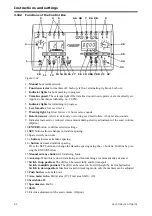
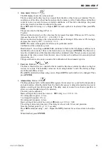
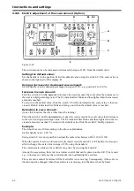
4 Area meter. Button 13.
The RH display shows the value entered.
The area meter on the Box receives a signal from the drive wheel once per rotation. The cir-
cumference of the drive wheel has been stored in the memory of the Control Box and the Box
converts to area covered. In loose or cloddy conditions, or if the drive wheel slips, the preset
value may need to be altered to obtain the true area.
Press SET and alter using + or -. Repeat SET for each symbol to be altered. Then press EN-
TER.
The preset value for the Rapid P is 2.4.
To alter:
If the area shown is too low, the value must be increased. Example: If the area is 10% too low,
increase the value by 10% of 2.4 = (2.4+0.24) = 2.64.
If the area shown is too large, the value must be reduced. Example: If the area is 10% too high,
decrease the value by 10% = (2.4-0.24) = 2.16.
NOTE!
The same value applies for all sizes of a particular model.
Calibration of the automatic system
Hold button 13 for as long as AUtO CAL continues to flash in the LH display and 0 (zero) in
the RH. Drive for exactly 100 m in the field to be sown. Then press ENTER. The Box calcu-
lates the circumference of the wheel and shows the calculated value. This gives a more accurate
measure of the area covered from the start, since it takes soil conditions into account (wheel
slip, stones, etc.)
The speed shown is also more accurate after calibration of the automatic system.
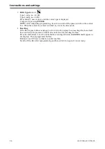
5 Fan revs. Buttons
and
.
The Box is fitted with a rev counter for the fan and the Box has an alarm for either too high or
too low rev counts. The boundary values can be set using buttons 7 and 8. The factory settings
are 3800 and 4800 revs/min.
Press SET and alter the values using + and -. Repeat SET for each number to be changed. Then
press ENTER
6 Alarm delay. Button 10
The Box produces both visible and audible signals. An incorrect rev count for the fan produces
an instant alarm, while the alarm from the feed roller sensor is delayed somewhat to prevent
alarms occurring at low driving speeds. This delay must of course be as short as possible to
allow even short sudden stops to be detected.
The delay can be adjusted.
Basic setting of the control box version
15 (mfg. no. -10 133) = 10
10 correspond to approx. 1,5 sec.
5 correspond to approx. 0,5 sec.
30 correspond to approx. 4,0 sec.
Basic setting of the control box version
(mfg. no. 10 134-) = 1.0
The setting is done real-time (sec.). The delay can be set with 0.1-second precision.
Note the decimal point! E.g. 1.0 = 1 seconds
Press SET and adjust using + and -. Repeat the SET procedure for each new item to be adjus-
ted.
When finished, press ENTER.
Summary of Contents for RAPID RD F Series
Page 1: ...Ver 1 3 07 06 01 900107 en Instructions Seed drill RAPID series RD 300 450 F No 10 026 11 999...
Page 2: ...2 Ver 1 3 07 06 01...
Page 6: ...6 Ver 1 3 07 06 01...
Page 16: ...Assembly instructions 16 Ver 07 06 01 07 06 01...
Page 23: ...RD 300 450 F Ver 1 3 07 06 01 23...
Page 41: ...RD 300 450 F Ver 1 3 07 06 01 41...
Page 47: ...RD 300 450 F Ver 1 3 07 06 01 47...
Page 108: ...Appendices 108 Ver 07 06 01 07 06 01 7 4 Electrical diagram Figure 7 8 307335...


