Advice on sowing
70
Ver.07/06/01 07/06/01
4.2
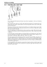
Checking the seed feed
Figure 4.2
The seed feed should be checked at the same time as the sowing depth, i.e. after every 4 hectares
or once an hour.
When checking the seed feed, you must ensure that the drill appear to be delivering the same
quantity from each coulter. Lift the machine to the low-lift position. Then set the low-lift switch
to the full-lift position.
Manually turn the drive wheel one full turn when the fan is not running (for safety reasons). Then
start the fan and check that the seed has been blown out. If you are not sure whether the seed has
blown out, repeat this procedure.
Start with tramlining activated and with all coulters except those switched off for tramlining deli-
vering seed. Then advance past the tramlining function and check if these coulters are now deli-
vering seed.
Get into the routine of quickly looking over the drive shafts, gears and chains to see that everyth-
ing looks normal and is still in place. Check regularly that the seed feed roller is rotating at a con-
stant speed by checking the indicator lights, see “Figure 3.43” point 8.
This sowing system has been developed to deliver even seed feed and reliable sowing rates. Vä-
derstad-Verken AB shall not be held liable for any claims for indirect or consequential damages
relating to losses incurred in connection with the use of the drill. In addition Väderstad-Verken
AB accepts no liability for losses arising from incorrect use of the sowing or seed feed functions
of the drill or any part thereof.
It is the responsibility of the operator to use properly pre-treated seed, treated with dressings which
do not impair or prevent seed feed. Note that the use of seed types larger than normal pea seed can
block the seed feed system.
Summary of Contents for RAPID RD F Series
Page 1: ...Ver 1 3 07 06 01 900107 en Instructions Seed drill RAPID series RD 300 450 F No 10 026 11 999...
Page 2: ...2 Ver 1 3 07 06 01...
Page 6: ...6 Ver 1 3 07 06 01...
Page 16: ...Assembly instructions 16 Ver 07 06 01 07 06 01...
Page 23: ...RD 300 450 F Ver 1 3 07 06 01 23...
Page 41: ...RD 300 450 F Ver 1 3 07 06 01 41...
Page 47: ...RD 300 450 F Ver 1 3 07 06 01 47...
Page 108: ...Appendices 108 Ver 07 06 01 07 06 01 7 4 Electrical diagram Figure 7 8 307335...

