Troubleshooting
100
Ver.2 01.11.2002
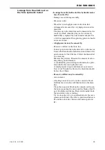
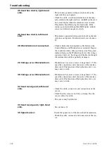
25 Seed box clutch, right-hand
side.
- This alarm is generated when seed shut-off on the
right side does not operate.
- Check the cable, switch and connection of the mag-
netic clutch in the right seed box. An LED on the seed
box switch lights when the clutch receives current.
The clutch should then stop the feed roller. If the
alarm is generated although the LED lights, a likely
cause is a defective magnetic clutch.
26 Seed box clutch, left-hand
side.
- This alarm is generated when seed shut-off on the left
side does not operate. For other details, see alarm no.
25.
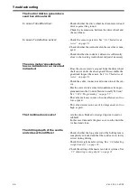
28 Workstation not connected.
- Check whether the intermediate cable between the
Control Station and Workstation is connected. Inspect
the condition of the cable and connectors. The green
indicator lamp on the Workstation shows that voltage
is present, however, the lamp could light even though
the intermediate cable is partially damaged.
29 Voltage error Workstation 1.
- Workstation 1 receives a lower voltage than 11 V. In-
spect the connections and connectors of the interme-
diate cable. The function of the hydraulic valves, etc.
may cease to work.
30 Voltage error Workstation 2.
- Workstation 2 receives a lower voltage than 11 V. In-
spect the connections and connectors of the interme-
diate cable. The function of the hydraulic valves, etc.
may cease to work.
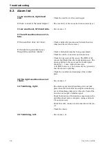
32 Seed level guard, left-hand
side.
- Check the cable, connectors and connections of the
sensor.
- Check that the sensor is not dirty or damp. Dry the
sensor with a dry cloth.
- The sensor may be defective.
33 Seed level guard, right-hand
side.
- See alarm no. 32.
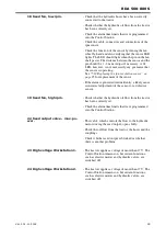
39 Speed sensor.
- Check the rpm sensor of the drive wheel transmission.
- Check the cable, connector and connection of the sen-
sor.
Summary of Contents for RAPID RDA S Series
Page 1: ...Ver 2 01 11 2002 900225 en Instructions Seed drill RAPID series RDA 500 800 S No 12 000 12 799...
Page 2: ...2 Ver 2 01 11 2002...
Page 4: ...4...
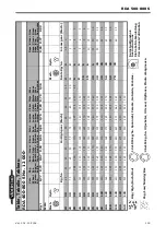
Page 73: ...RDA 500 800 S Ver 2 01 11 2002 73...
Page 75: ...RDA 500 800 S Ver 2 01 11 2002 75 Figure 5 4...
Page 105: ...RDA 500 800 S Ver 2 01 11 2002 105...
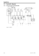
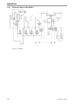
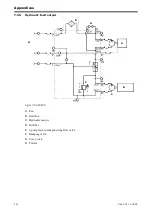
Page 108: ...Appendices 108 Ver 2 01 11 2002 7 3 2 Hydraulic diagram RDA 800 S Figure 7 2 428718...
Page 121: ......

