RDA 600-800 S
Ver.3 29/06/07
111
6.4.6
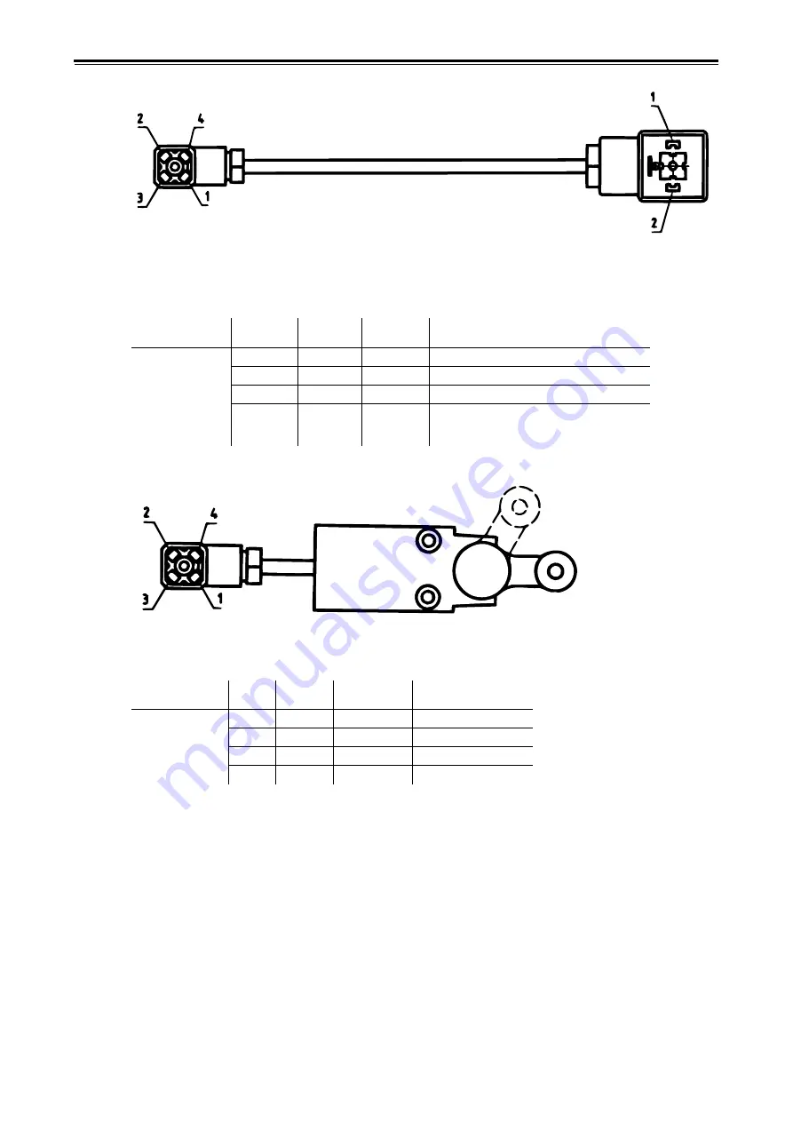
Hydraulic electric valves
Figure 6.10
6.4.7
Boundary switches
Figure 6.11
Table 6.9
Workstation
connection
Terminal
(A)
Cable
colour
Terminal
(B)
Function
WS1-12
WS1-14
WS1-15
WS1-18
WS1-19
WS1-20
WS1-21
1
2
Brown
1
12 V supply to valve, red lamp lights
3
4
Blue
2
0 V
Table 6.10
Workstation
connection
Pole
Cable
colour
On
(pos. B)
Function
WS1-9
1
Brown
0 V
On = signal
2
3
4
Blue
0 V
0 V
A
B
B
A
Summary of Contents for RAPID RDA S Series
Page 1: ...Ver 3 29 06 07 900236 dk Instruktioner S maskine RAPID serie RDA 600 800 S Nr 12 800 14 799...
Page 2: ...2 Ver 3 29 06 07...
Page 17: ...RDA 600 800 S Ver 3 29 06 07 17...
Page 20: ...Instructions and settings 20 Ver 3 29 06 07 2 8 Horizontal alignment Figure 2 18 A E C D B...
Page 71: ...RDA 600 800 S Ver 3 29 06 07 71 Figure 4 4...
Page 104: ...Appendices 104 Ver 3 29 06 07 6 3 2 Hydraulic diagram RDA 800 S Figure 6 2 444639...
Page 116: ...Appendices 116 Ver 3 29 06 07...
Page 117: ......


