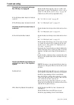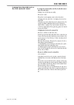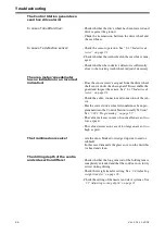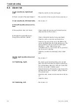
Maintenance and service
84
Ver.2 01.11.2002
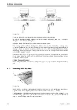
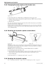
5.14 Changing the valve seals on the master ram
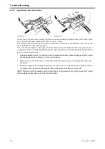
Figure 5.23
A
Unscrew the guide (C) carefully if there is still hydraulic pressure in the system
B
Change O-ring (A) and also O-ring (B) on the guide if necessary.
NOTE!
O-ring (A), Part No.
404796 is of extra hard quality.
C
Refit the valve.
The valve on the underside of the master ram shuts off the oil flow from the ram once the drill has
been lowered to the chosen working depth.
Working depth is set using the depth stop (A) which governs the valve via the valve rod (D). If the
depth stop moves along the piston rod so that working depth gradually increases during work, the
valve is probably leaking.
5.15 Bleeding the hydraulic system accumulators
NOTE!
Before starting service work on the part of the hydraulic system controlling the folding and
weight transfer system, drain all oil from the accumulator!. When the accumulators are drained,
the manometer pressure should be zero.
NOTE!
During service work on the hydraulic system the drill must always be unfolded.
A
Turn the weight transfer lever from A to B.
B
Raise the drill to the top position. Release the pressure from the folding system of the drill us-
ing the hydraulic controls. Check that the pressure showing on the manometer is zero.
C
Lower the drill again.
To reset the pressure, see
”3.8 Adjusting weight transfer” on page 32.
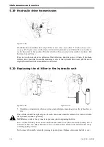
5.16 Bleeding the hydraulic system
See ”
3.7 Adjusting sowing depth” on page 31
and ”
3.10 Adjusting the tool bars” on page 34
.
Figure 5.24
Figure 5.25
A
C
B
D
Summary of Contents for RAPID RDA S Series
Page 1: ...Ver 2 01 11 2002 900225 en Instructions Seed drill RAPID series RDA 500 800 S No 12 000 12 799...
Page 2: ...2 Ver 2 01 11 2002...
Page 4: ...4...
Page 73: ...RDA 500 800 S Ver 2 01 11 2002 73...
Page 75: ...RDA 500 800 S Ver 2 01 11 2002 75 Figure 5 4...
Page 105: ...RDA 500 800 S Ver 2 01 11 2002 105...
Page 108: ...Appendices 108 Ver 2 01 11 2002 7 3 2 Hydraulic diagram RDA 800 S Figure 7 2 428718...
Page 121: ......

