VAG Operation and Maintenance Instructions • 6
4.3 Installation position
The VAG DUOJET
®
Automatic Air Valve must always
be installed in an upright position. If installed in any
other position, the manu-facturer cannot ensure the
trouble free functioning of the valve or station (see Pic-
ture 10 - following page).
4.4 Installation note
Observe the following special installation notes in ac-
cordance with the specified hydraulic conditions and
installation positions.
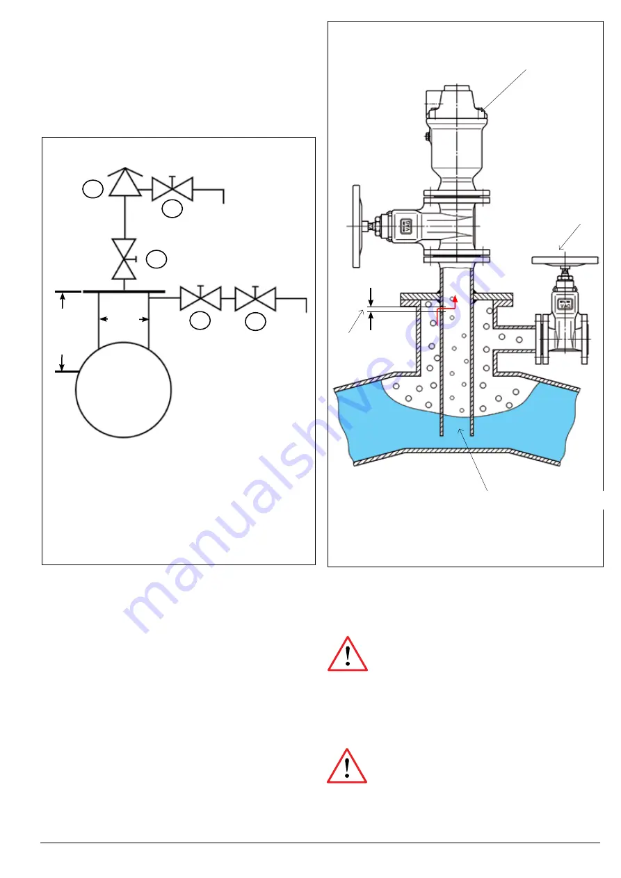
4.2.2 Installation for pipelines ≥ DN 600
For pipelines ≥ DN 600 the venting dome should not fall below
nominal size DN 600 and a height of h = 600 mm. In this case a
sufficiently dimensioned venting dome is provided.
To avoid a large installation height, manual venting can also be at-
tached laterally to the air dome. Here, however, a second central
stop valve upstream from manual venting is necessary.
≥
600 mm
~ DN 600
1
2
3
4
1
: Venting valve
2
: Manually operated air inflow and release, flush
valve
3
: Central stop valve
4:
Additional flush and discharge valve
4.2.3 Water flow rate
The water flow rate ascertained to fill a pipeline is equivalent to the
volume of air to be released. In this case venting should take place
at an overpressure of a maximum of 0.3 bar. In doing so, a change
in the density of the air can still be accommodated .
If when filling the rate in the pipeline exceeds 0.25 m/s, a dome
construction with an immersion pipe is recommended to reduce
pressure surges (Picture 9).
The water flow rate ascertained to empty a pipeline is equivalent
to the volume of air to be fed. In this case aeration should take
place at an underpressure of a maximum of 0.4 bar relative pres-
sure. In doing so, a change in the density of the air can still be
disregarded.
Picture 8: Pipeline
≥
DN 600
Picture 9: Dome construction with immersion pipe
3
VAG DUOJET
®
Automatic Air Valve
Manually operated
gate valve for air
inflow and release
Diameter:
DN
/
10
Immersion pipe


