


VAG Operation and Maintenance Instructions • 12
If valves are installed without gear units it must be ensured that
the valve is not pressurised.
•
Warning:
Uncontrolled rotation of the valve shaft!.
Danger of damage to the VAG Butterfly Valve / Pipeline
system! Death or serious injury can result if body parts or
pieces of clothing get caught up in rotating shaft.
- Never operate the butterfly valve without gearbox in a pres-
surised pipeline!
- Make sure that no pressure is in the pipeline when you dis-
mantle the gearbox from the valve!
For detailed information on gears and actuators, please refer to
the operation manuals issued by the manufacturers of these com-
ponents (e.g. AUMA, Rotork).
The VAG EKN
®
Butterfly Valve has an adjustment angle of 90°.
The valve itself is not equipped with position limiters.
The actuator must be equipped with limit stops. The actuator
must be designed so that it turns counter-clockwise in relation to
the valve shaft!
The limit position adjustment is to be done in compliance with
the operating manuals issued by the respective gear manufactu-
rers, such as AUMA, Rotork etc. In case a gear is retrofitted, its
nominal torque and the adjustment of the limit stops “OPEN” and
“CLOSE” must be adapted to the valve.
Non-compliance with these regulations may endanger life and
limb and/or cause damage to the pipeline system. If actuators
powered by external sources of energy (electric, pneumatic or hy-
draulic) have to be disassembled from the valve, the safety inst-
ructions under Section 1.1 needs to be observed and the external
source of energy must be switched off and isolated.
6.2 Operating torques
Operating torques are the maximum required torques acting on
the actuator stem at full differential pressure including a safety
factor of 1.5. If required, you can contact us for information about
the respective torques and/or controlling torques for electric ac-
tuators.
6.3 Emergency manual operation (handwheel)
•
Caution:
If the valve is operated via the handwheel of the
electric multiturn actuator, the torque switches do not have any
safety function.
Operation via the emergency handwheel is intended for short peri-
ods only, for commissioning and for exceptional situations.
The emergency handwheel is not suitable for continuous opera-
tion.
If, in intermediate position, a foreign body gets jammed in the
valve, this may result in higher operating forces – especially with
heavily geared down actuators – which in turn may damage the
actuation components. Therefore:
If you meet any resistance while operating the valve with the emer-
gency handwheel, turn the handwheel in the opposite direction for
some turns and then turn it in the direction again in which the
disturbance was found (washing out of the foreign body). Conti-
nue operation very carefully, never use excessive force and repeat
washing, if necessary.
6.4 Assembly of the electric actuator
The electric actuator is mounted to the input flange of the gear
unit. The actuator size is selected according to the maximum ac-
tuation elements.
The valve is switched off:
• position-dependent in Open position
• position-dependent in Closed position
The switch settings are factory-adjusted. The torque switches
serve as overload protection in the intermediate positions. If the
valve is retrofitted with an electric actuator, the position switches
have to be adjusted after the actuator has been mounted. For the
adjustment procedure, please refer to the operating manual issu-
ed by the manufacturer of the electric actuator.
The relevant safety regulations and the instructions of the manu-
facturer of the electric actuator must be observed.
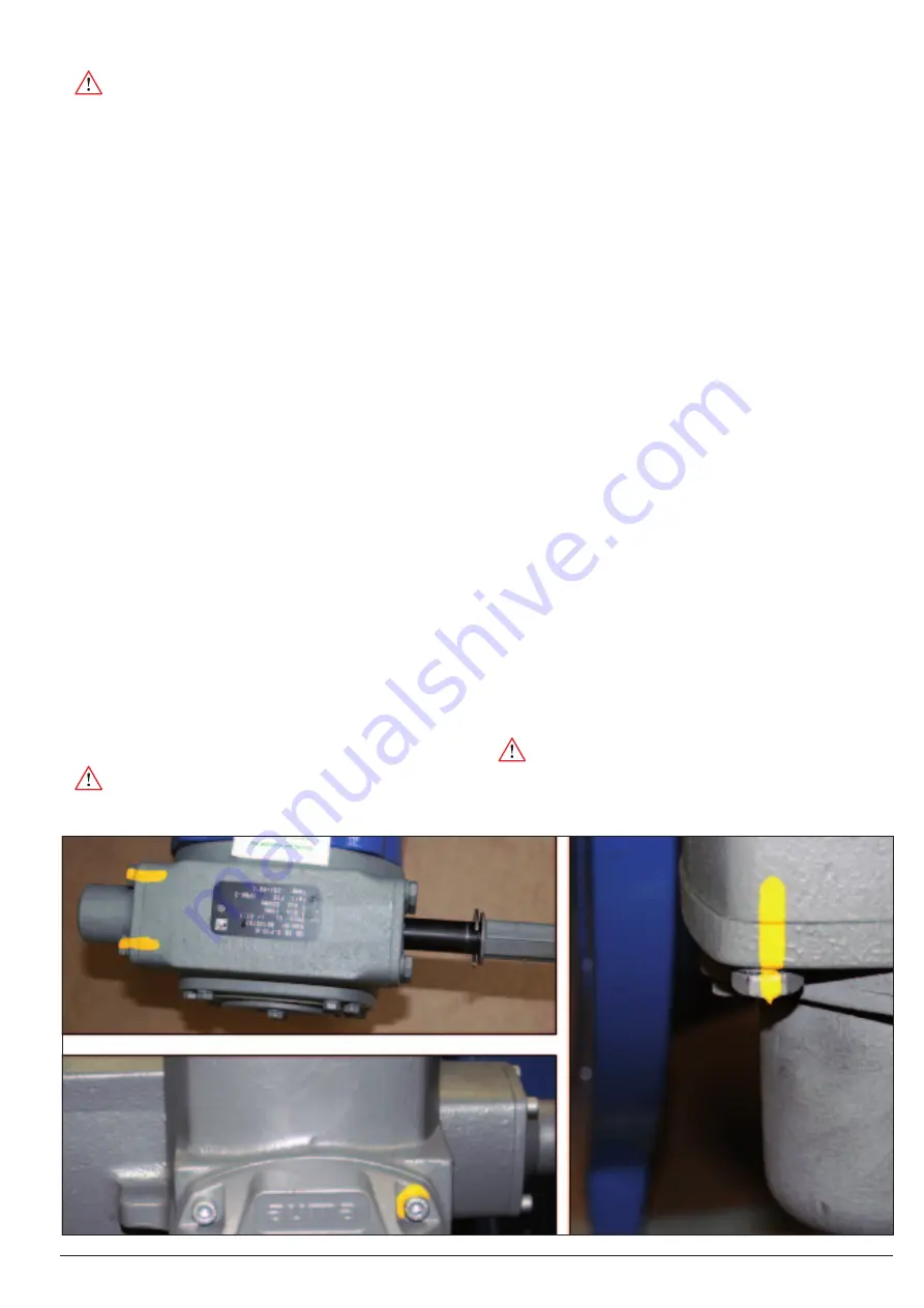
When the items are delivered, the adjustment screws and the
connection bolts of the gear and the electric actuator are sealed
with labels and/or identified by colour markings. The removal
or breaking of these identifications will result in the loss of the
manufacturer’s warranty.
•
Caution:
Non-observance of the warnings and notes may
result in serious injuries or damage. Qualified personnel must be
thoroughly familiar with all warnings and notes in these opera-
tion instructions.
Picture 10: Gearbox markings


