background image

7.2  Inspection and operation intervals

The valve should be checked for tightness, proper operation and 

corrosion protection “at least once per year”  (DVGW Instruction 

Sheet W 

392

).

In case of extreme operating conditions inspection should be per-

formed more frequently.

7.3  Maintenance work and replacement of 

 parts

7.3.1 Design

The design view in Picture 12 serves as a partial overview for the 

descriptions of the working steps below. For information about 

spare parts and their part numbers, please refer to the document 

VAG KAT 1310-E.

7.3.2  Recommendations for the replacement 

of parts

Profile seals and O-rings must be replaced whenever necessary. 

The replacement intervals depend on the operating conditions. 

7.3.3  Cleaning and lubrication

When being replaced, the profile seal and the O-rings should al-

ways be lightly greased. Use lubricants with approval for applica-

tion with foodstuffs or drinking water. 

Recommended lubricants:

For the profile seal and the O-rings: KLÜBERSYNTH VR 69-252 

(with KTW approval for drinking water) Manufacturer: Klüber 

Lubrication München AG, Germany.

7.3.4  Replacement of the profile seal

Due to the double-eccentric bearing, the profile seal can be re-

placed without disassembly of the disk. Valves of up to DN 1000 

must either be completely dismantled from the pipeline or at least 

disconnected from the pipeline on one side to replace the profile 

seal. In the same way as for the installation of the disk, all safety 

precautions need to be taken.
Disassembly of the sealing ring:
• Open the disk (2) until the profile seal (3) emerges from the body
• Unfasten the retaining ring screws (5.1)
• Remove retaining ring (1) and sealing ring (3)
• Clean the disk (2) in the sealing zone
• Check the seat ring in the body for damage or deposits
• Insert the new sealing ring into the groove of the disk and slight-

ly grease it with KLÜBERSYNTH VR 69-252

• Insert the hexagonal screws (5.1) and fasten them using the

torque specified in Table 1 (Section 7.3.6 Tightening torques

for screws)

7.3.5  Replacement of the O-rings in the 

 bearing

For this kind of maintenance work, the valve must be depressu-

rised.
• Turn the butterfly valve (2) into closed position
• Unfasten the hexagonal nuts at the gear flange and pull the gear

off the shaft (7)

• Loosen the threaded pin and pull off the coupling. Pull the ad-

justment spring (20) off the shaft

•  In the depressurised pipeline, the hexagonal screws (14) are

unfastened and the bearing flange (10) as well as the bearing

cover (11) are pulled off. Slightly grease the O-rings (17 / 16) with

KLÜBERSYNTH VR 69-252 before installation.

• Reassembly is done in reverse order
• Tighten the hexagonal screws (14) only slightly to prevent ten-

sioning the bearing bush (12) on the disk (2). Secure the flange

position using the threaded pins (15).

•  Assemble the adjustment spring (20) and the coupling
• Before mounting the gear, check whether the disk position and

the gear position match

• Fasten the gear fixing screws using the tightening torques spe-

cified in Table 3

• If necessary, readjust the limit stop of the gear. The limit stop

must only be adjusted when the valve is in closed position.

AUMA worm gear units are adjusted as specified in the AUMA

VAG Operation and Maintenance Instructions • 16

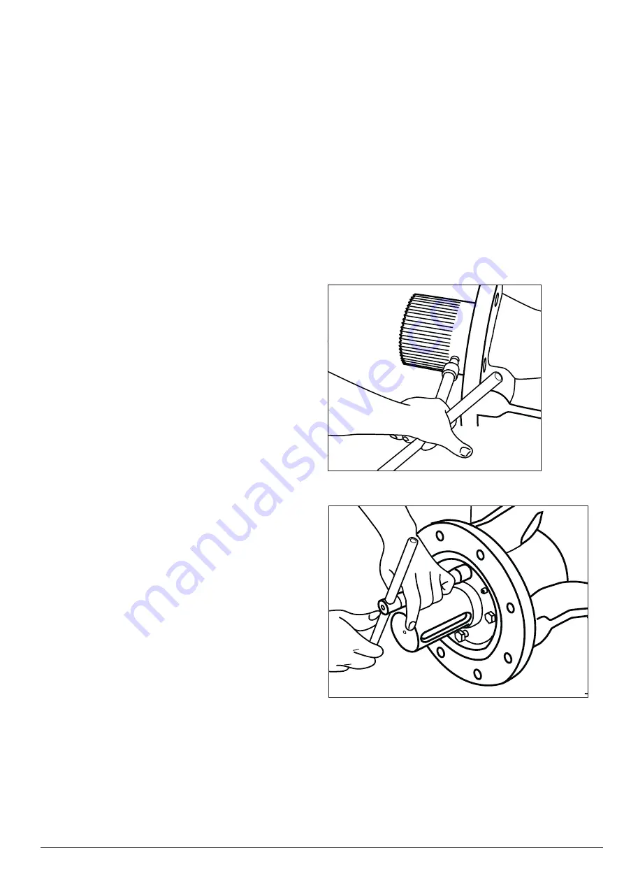
Picture 18: Replacement of O-ring - Step 1

Picture 19: Replacement of O-ring - Step 2

Summary of Contents for EKN H-Series

Page 1: ...KAT 1310 B Edition 6_21 03 17 Operation and Maintenance Instructions VAG EKN Butterfly Valve H M and B Series...

Page 2: ...eam of the valve 8 4 2 2 Gear positions 10 4 3 Installation position 11 4 4 Assembly instructions and fittings 12 5 Set up and operation of the valve 12 5 1 Visual inspection and preparation 12 5 2 Fu...

Page 3: ...luid may emerge from the pipeline or the valve The pipeline must be emp tied completely before the valve is dismantled Special care needs to be taken in case of residue which may continue flowing 1 2...

Page 4: ...y Valve For valves that have been factory packed in transport crates wooden crates the centre of gravity of the entire unit must be taken into account The centre of gravity is marked on each side of t...

Page 5: ...an be calculated either using the VAG UseCAD Planning Software or the following calculation rules Cavitation limits After the upstream and downstream pressures of the valve as well as the flow rate ha...

Page 6: ...ssure applied to the closed valve must not exceed its rated pressure The VAG EKN Butterfly Valve has its limit stop in the gearbox This stop limits both the open and the closed position Due to the aut...

Page 7: ...perational pressure of the medium is maintained on the opposite side of the disk The UVV lock is operated by pushing the movable bolts when required with a handwheel radially in the direction of the p...

Page 8: ...assembly in drinking water pipelines suitable sealing mate rials lubricants and process materials must be used which are approved for use in drinking water pipelines Before putting the valve into oper...

Page 9: ...Valve at elbows and branches unfavourable ideal 3 X DN EKN EKN favourable EKN When installing a butterfly valve downstream of a control valve or a plunger valve make sure that there is enough space b...

Page 10: ...ation of the VAG EKN Butterfly Valve 4 2 2 Gear positions The gear can be turned by 90 around the drive shaft A Flow on shaft side seat surface on the outlet side gear on the right B Flow on the side...

Page 11: ...al position without restrictions with the gear facing up or down in the pipelines In case of valves with larger nominal diameters a special design of the valve must be selected due to the load of the...

Page 12: ...e it is connected to are aligned and level with each other Welding works on the pipeline must be performed be fore the valves are installed to prevent damage to the seals and the corrosion protection...

Page 13: ...to be observed and the external source of energy must be switched off and isolated Special care needs to be taken in case of hot surfaces Touching hot surfaces may result in burns Even when the de vic...

Page 14: ...G EKN Butterfly Valve with VAG HYsec hydraulic brake and lift unit 7 1 General safety instructions Prior to the performance of inspection and mainte nance work on the valve or its assemblies shut off...

Page 15: ...M and B Design and sub assemblies VAG Operation and Maintenance Instructions 15 A A B B C C D D E E F F Fuer diese Unterlagen behalten wir uns alle Rechte auch fuer den Fall der Patenterteilung und de...

Page 16: ...ofile seal 3 emerges from the body Unfasten the retaining ring screws 5 1 Remove retaining ring 1 and sealing ring 3 Clean the disk 2 in the sealing zone Check the seat ring in the body for damage or...

Page 17: ...es of retaining ring screws Picture 23 Tightening torques of retaining ring screws Bearing flange fixing screws Table 2 Tightening torques of bearing flange fixing screws Picture 24 Anzugsmomente Lage...

Page 18: ...n matter Gear blocked Undo block No electrical connection of elec tric actuator Establish electrical connection Unfavourable flow and impair ment of movement Change installation position Leaks in the...

Page 19: ...arl Reuther Str 1 68305 Mannheim Germany Phone 49 621 749 0 Fax 49 621 749 2153 info vag group com http www vag group com Service Our service hotline can be reached 24 7 world wide In case of emergenc...

Reviews: