VAG Installation and Operating Instructions • 7
The now operational VAG EROX
®
plus
Penstock must be cleaned
from drilling dust and drilling residues, in particular the inner area
between the frame and the gate as well as the thrust wedges.
4.2.2 Assembly of the VAG EROX
®
plus
Penstock; Control distance measure of slide
plate
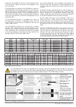
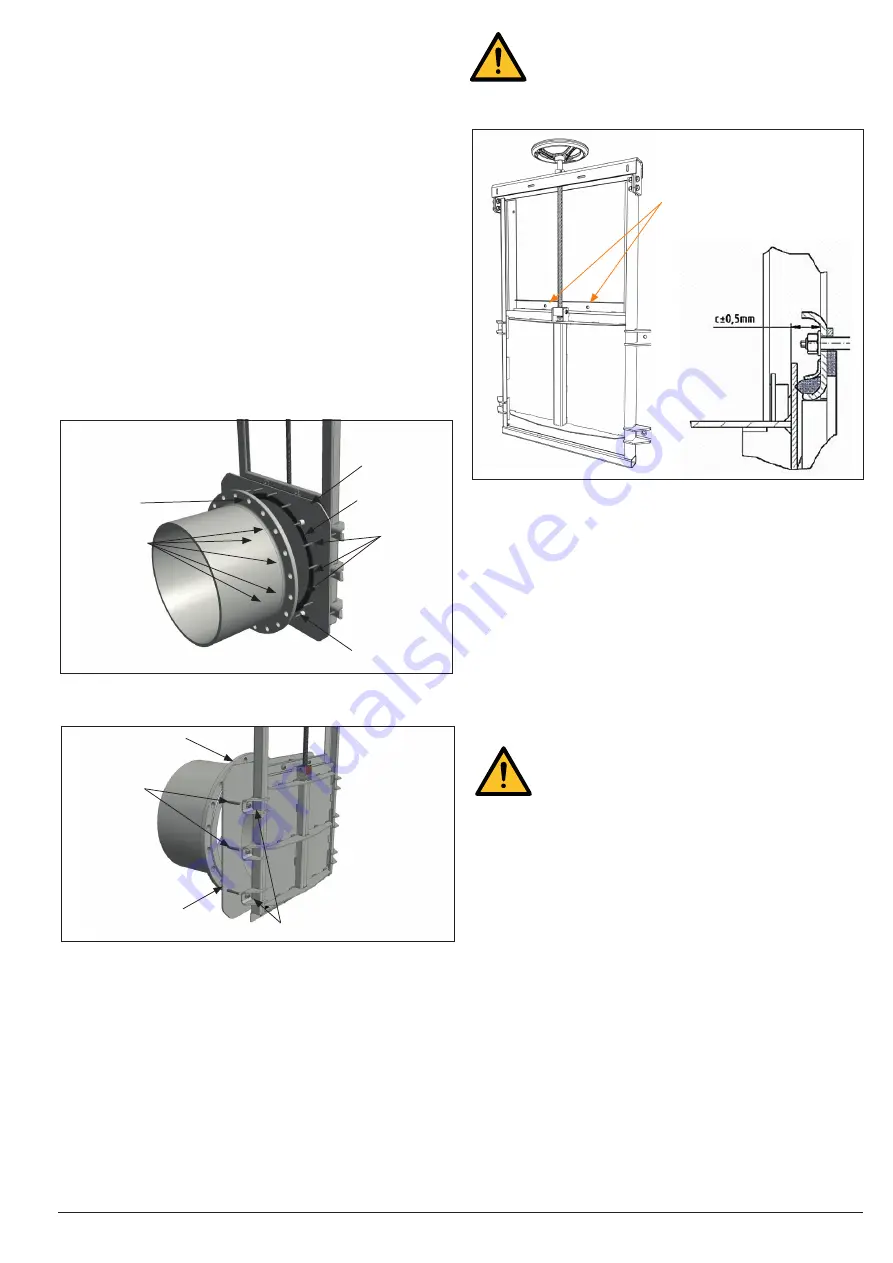
When mounting the anchor rods for the upper mounting holes
(see picture 9), attention must be paid to compliance with the dis-
tance dimension C (see table above) due to the risk of collision
between the slide plate and the anchor rod.
Tighten the nuts on the upper anchor rods so that the distance C
between the slide plate and the cross member is largely the same
over the entire width. By slightly opening the slide plate, check if
it opens without collision.
4.2.3 Assembly of the VAG EROX
®
plus
Penstock on a pipe flange (EROX
®
plus
version
with flange adapter)
The version VAG EROX
®
plus
has a flange adapter and is inten-
ded for attachment to a pipe flange EN 1092-2 PN 10. In sizes DN
150 up to and including DN 600, the VAG EROX
®
plus
is connec-
ted to the pipe flange via a flange adapter.
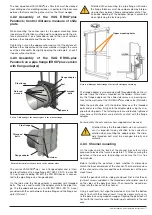
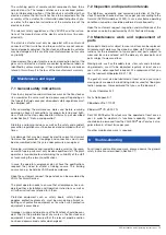
On the tube side, the flange adapter is provided with threaded
bolts. They are used to mount the adapter plate to the pipe flan-
ge. The threaded bolts are acc. to DIN EN 1092-2, PN 10. A seal
provided with the seal between the pipe flange and the flange ad-
apter (Picture 7).
Attention! When mounting to a pipe flange with collar,
the flange thickness must be compensated by interpo-
sing washers between flange and adapter plate. Thus,
an undue bending of the adapter flange is prevented
when tightening the fastening nuts.
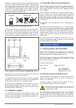
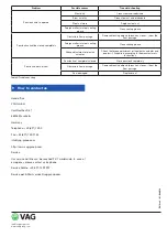
The flange adapter is also provided with threaded bolts on the sli-
de side. Here, the slider is mounted on the holders. After assem-
bly, the flange adapter on the slide side serves as a bearing sur-
face for the wall seal of the VAG EROX
®
plus
slide valve (Picture 8).
Slide the spindle slide with the holder holes over the threaded
bolts and screw them firmly onto the adapter plate using the sup-
plied fastening parts. The fastening nuts are alternately tightened
crosswise until all holders are in metallic contact with the flange
adapter.
For assembly, the nuts and washers supplied must be used.
Attention! Since the threaded bolts are not symmetri-
cal, it is important to pay attention to the correct ori-
entation when mounting the adapter plate. The slide-
side threaded bolt must be arranged laterally and
vertically.
4.2.4 Channel mounting
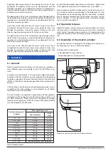
On the sides and in the invert of the channel, box outs must be
prepared to receive the frame (see picture 11). When securing the
penstock in the box outs for grouting, make sure that it is free
from tension.
Before installing the penstock, check whether its dimensions
match the inner dimensions of the channel. The inner dimensions
of the channel must not exceed the outer dimensions of the pen-
stock frame.
Install the penstock with its slide gate closed. First install the ad-
justment screws supplied in the threaded anchor plates located
on the sides of the penstock frame. Then lower the closed pen-
stock into the box out of the channel.
Using a spirit level, first align the penstock sill so that the bottom
seal is flush with the channel invert. It may be necessary to secu-
re the penstock using wooden wedges. Aligning the penstock sill
flush with the invert prevents the build-up of sediments in the seal
area.
Picture 9: Montage Ankerstangen für obere Befestigungsbohrung
Upper mounting holes
Pipe flange
Threaded
bolts
Flange adapter
Retainer
Picture 8: Assembly of the penstock on the adapter plate
Pipe flange
Nuts and
washers
Picture 7: Mounting of the adapter plate to the pipeline flange
Seal
Spacers
Threaded
bolts
Flange adapter


