14
5.9.2 Lesekopf LB-15
Ausgangsformat SSI
Graycode / Binärcode
Im Sensor wird ein Schieberegister
permanent mit dem aktuellen Messwert
geladen. Wenn ein Datenwert gelesen
werden soll, gibt die Steuerung ein Taktpaket
(25 Bit) auf der Clockleitung aus. Die erste
fallende Flanke steuert ein Monoflop im
Sensor an, dass das Schieberegister vom
parallelen Laden in serielle Ausgabe
umschaltet. Bei jeder folgenden steigenden
Taktflanke wird jetzt ein Datenbit ausgege-
ben. Wenn das niederwertigste Bit empfan-
gen wurde, wird der Takt gestoppt. Das
Monoflop, das von den Taktpulsen immer
nachgetriggert wurde, fällt nach Ablauf der
Schaltzeit wieder in den Grundzustand und
erlaubt wieder die Übernahme der Messwer-
te in das Schieberegister. Die Datenleitung
wird bis dahin auf Low-Pegel gehalten.
Wenn der Takt nicht für die Zeit Tm-T/2
unterbrochen wird (Ausgabe von weiteren
25 Perioden), taktet das Schieberegister
erneut den gleichen Datenwert heraus
(Fehlererkennung in der Auswertung). Eini-
ge Geberverfügen über ein Power Failure
Bit (PFB). Achtung: Beim APOS LB15 ist
das PFB immer „LOW“!
PFB = Power Failure Bit
T =
Periodendauer des Taktsignals
Tm = Monoflopzeit > 10μs
max. Taktrate
울
150 kHz
position (n)
position (n + 1)
t
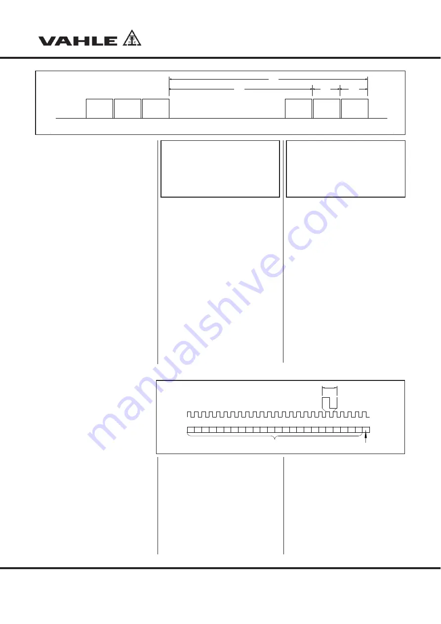
b2
t
r
t
b1
t
b0
byte 2
(msb)
byte 0
(lsb)
byte
byte 2
(msb)
byte 0
(lsb)
byte
G23
Legende G23
RS 485 Zeitdiagramm
tb2 (tbyte2) = 8,85 ms
tb1 (tbyte1) = 0,57 ms
tb0 (tbyte0) = 0,57 ms
tr (trate) = 10 ms
Legend G23
RS 485 time diagram
tb2 (tbyte2) = 8.85 ms
tb1 (tbyte1) = 0.57 ms
tb0 (tbyte0) = 0.57 ms
tr (trate) = 10 ms
5.9.2 Reading head LB-15
Source format SSI
Graycode / Binärcode
A shift register with the current measured
value is permanently loaded in the
sensor. If a data value is to be read, the
control outputs a clock package (25 bit) on
the clock line. The first falling edge activates
a monoflop in the sensor, which switched
the shift register from parallel loading to
serial output. A data bit is now output for
each following rising clock edge. After the
least significant bit has been received, the
clock pulse is stopped. The monoflop,
which was always re-triggered by the clock
pulses, returns to its basic condition after
expiration of the switching time and again
enables the adoption of the measured
values into the shift register. Until then the
data line is kept at low level.
If the clock pulse is not interrupted for
the time Tm-T/2 (output of further 25 cycles),
the shift register again clocks out the
same data value (error recognition in the
evaluation). Some encoders have a
Power Failure Bit (PFB). Caution: The
PFB on the APOS LB15 is always
“LOW“!
PFB = Power Failure Bit
T =
Cycle duration of the clock signal
Tm = Monoflop time > 10μs
max. clock rate
울
150 kHz
23 22 21 20 19 18 17 16 15 14 13 12 11 10
9
8
7
6
5
4
3
2
1
0
PFB
24 Datenbits/3Bytes
24 data bits/3 bytes
T
Datanprotokoll: Auslesen der Daten (mit 25 Takten)
Data protocol: Data readout (with 25 clock pulses)
Impulsdiagramm der Datenübertragung
G24
APOS KBH - MKL
Montage und Bedienungsanleitung
Installation and operation instructions


