APOS KBH - MKL
9
Montage und Bedienungsanleitung
Installation and operation instructions
G10
G11
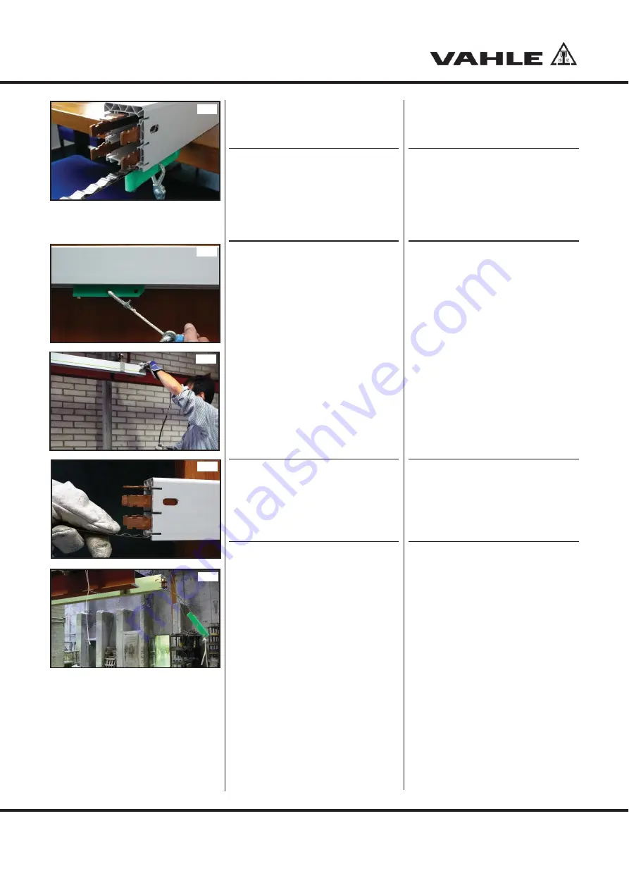
Den Rutscher in den Montage-
schacht der Schleifleitung einsetzen
(
G10
).
S
Achtung
:
Das Codeband muss beim
Einziehvorgang verschmut-
zungsfrei sein. Im Falle von
Verschmutzungen muss das
Band vor dem Einziehen gerei-
nigt werden, z.B. durch eine
Reinigungstuch laufen lassen.
Komponenten durch langsames so-
wie gleichmäßiges Ziehen einführen.
Der Winkel zwischen Schleifleitungs-
längsrichtung und Zugseil sollte unter
20 ° liegen (
G11
).
Das Code- sowie Führungsband ist
durch die zweite Montageperson zu-
führen. Dabei sind Handschuhe zu
tragen.
Während des Einziehvorgangs Code-
und Führungsband mit der einen
Hand gleichmäßig aus den Trans-
portboxen herauszuziehen und mit
der anderen Hand in den Montage-
schacht einzuleiten (
G12
).
S
Achtung
:
Codeband und Fixierprofil
langsam, etwas oberhalb des
Montageschachtes zuführen.
Die beiden einzelnen Profile
dürfen dabei nicht verdreht
sein (
G13
).
Beim Einzug auf einwandfreien Sitz
im Schacht achten. Falls erforderlich,
die Komponenten zurückziehen und
neu einbringen.
Am Anlagenende das Codeband ca.
10 cm aus dem Gehäuse herauszu-
ziehen und den Einziehrutscher
demontieren. Bei Bedarf das Band
auf der Gegenseite zurückziehen
(
G14
).
5.2 Festpunkt
Nach erfolgter Montage ist das
Codeband entsprechend Vorgaben
im Verlegungsplan zum Schleiflei-
tungsgehäuse festzusetzen. Dies
erfolgt normalerweise am Festpunkt
der Schleifleitung.
G12
G13
G14
Insert the threading tool into the
mounting shaft of the conductor line
(
G10
).
S
Attention:
The code strip must be free of
dirt. Clean the strip before in-
serting it if necessary, e.g. by
means of a cleaning cloth.
Insert the components by slow and
even pulling. The angle between the
longitudinal direction of the conduc-
tor line and the traction rope should
be below 20 ° (
G11
).
The code and guide strip must be
guided in by the second assembly
person. Gloves must be worn to do
so.
During the threading-in phase, evenly
pull the code and guide strip out of
the transport box with one hand, and
thread them into the assembly shaft
with the other hand (
G12
).
S
Attention
:
Slowly guide the code strip
and the fixing profile slightly
above the assembly shaft. The
two individual sections must
not be twisted while doing so
(
G13
).
Check the correct position in the
shaft when pulling in. If necessary,
pull the components back and thread
in again.
At the end of the system, pull the
code strip out of the housing by
approx. 10 cm and dismantle the
threading tool. If necessary, pull the
strip back on the counterside (
G14
).
5.2 Fixed point
After completing the assembly, fix
the code strip to the conductor line
housing in accordance with the
specifications in the installation
drawing. This normally takes place at
the fixed point of the conductor line.


