APOS
Montageanleitung
Mounting instructions
7
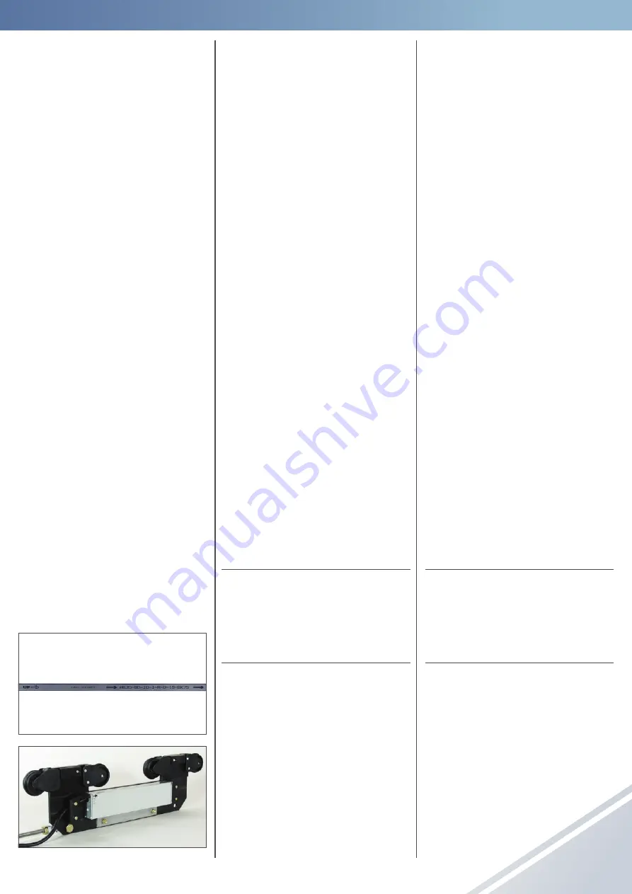
G01
G02
An beiden Schleifleitungsenden sollte etwa
0,5 m Freiraum zum Einziehen des Code-
bandes vorhanden sein� Die Endkappen
der Schleifleitung müssen demontiert sein�
4.1 Lieferumfang
• Codeband
• Fixierprofil
• Lesekopfwagen
Lesekopf (berührungslos)
• Zubehörset bestehend aus:
- linkem Anlagenende
- rechtem Anlagenende
- Festpunkt
• Einziehrutscher
Optionaler Lieferumfang
• Schnittstellenbaustein
• Streckeneinspeisung, (nur bei KBH-Nach-
rüstungen, falls erforderlich)
4.2 Werkzeug
• Schlitzschraubendreher
• Kreuzschlitzschraubendreher
• Maul- bzw� Ringschlüssel (7)
• Kombizange
• Seitenschneider
• Einziehrutscher
• 2 Paar Handschuhe
• Cuttermesser/Schere
Werkzeug optional:
• Handy, Funkgerät o� a� zur Verständigung
4.3 Einziehrichtung des Codebandes und
Fixierprofils
S
Achtung
!
Bei der Montage bzw� Einführen des
Magnetbandes in die Schleifleitung ist
auf die Markierungen am Magnetband
und am Sensorkopf zu achten�
Eine falsche Richtung liefert keine
korrekten Werte!
Die Pfeile auf dem Codeband (
G01
) und dem
Lesekopf (
G02
) geben die Zählrichtung des
APOS-Systems an� Der Pfeil auf dem Code-
band zeigt entgegen der Einziehrichtung
der Bänder�
There should be about 0�5 m space at the
ends of the conductor line for threading in
the code strip� The end caps of the conduc-
tor line must be dismantled�
4.1 Scope of delivery
• Code strip
• Fixing profile
• Reading head carrier
reading head (contactless)
• Set of accessories consisting of:
- left system end
- right system end
- fixed point
• Threading tool
Optional scope of delivery
• Interface module
• Line feed, (only for KBH retrofits, if nec-
essary)
4.2 Tools
• Slotted screwdriver
• Cross slot screwdriver
• Open-ended or box wrench (7)
• Combination pliers
• Side cutter
• Threading tool
• 2 pairs of gloves
• Cutter / scissors
Optional tools:
• Mobile phone, mobile radio set or similar
for communication
4.3 Threading in direction of the code strip
and the fixing profile
S
Attention!
During assembly or threading the mag-
netic strip into the conductor line, pay
attention to the markings on the mag-
netic strip and the sensor head�
An incorrect direction does not supply
correct values!
The arrows on the code strip (
G01
) and the
reading head (
G02
) indicate the counting
direction of the APOS system� The arrow
on the code strip points in the opposite
direction to the threading in direction of
the strips�


