KBSL • KSL • KSLT
5
Montageanleitung
•
Mounting instructions
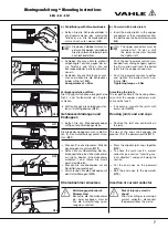
Halteeisen anbringen
Bringen Sie die Schraubkonsolen
oder Winkeleisen mit Langlöchern an.
H
Beachten Sie folgenden Monta-
ge-Abstände:
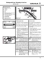
Aufhängeabstand max. 2000 mm
für Innenanlagen und überdachte
Aussenanlagen mit einer Umge-
bungstemperatur bis 35 °C.
Max. 1333 mm für Aussenanla-
gen, spez. Innenanlagen mit
hohen Umgebungstemperaturen
(>35-60 °C) und Anlagen mit Be-
heizung. Die erste und letzte Auf-
hängung ist mind. 250 mm und
max. 500 mm vom Teil stückende
anzuordnen. Der Abstand der
Gleitaufhängungen von dem Ver-
bindungsmaterial, den Endkap-
pen, Einspeisungen usw. muss
mindestens 250 mm bis max. 500
mm betragen, um die Ausdeh-
nung nicht zu behindern (
S2
).
Schleifleitung aufhängen
Verlegen Sie die Schleifleitung gerade
und parallel zur Kranbahn.
H
Die Schleifleitung muss sich von
den Festpunkten aus
unge -
hindert ausdehnen können. Zur
Erleichterung der Montage kann
das erste Teilstück mit zwei
Festaufhängungen festgesetzt
werden. Diese Aufhängungen
müssen nach Beendigung der
Montage durch Gleitaufhängun-
gen ersetzt werden.
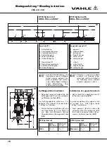
Montieren Sie bei gerader Verlegung
zwei Festaufhängungen etwa in der
Mitte der Anlage oder nach Verle-
gungsplan (
S1
) und (
S2
).
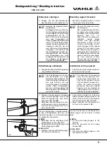
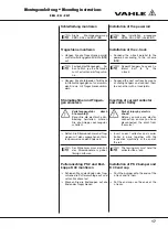
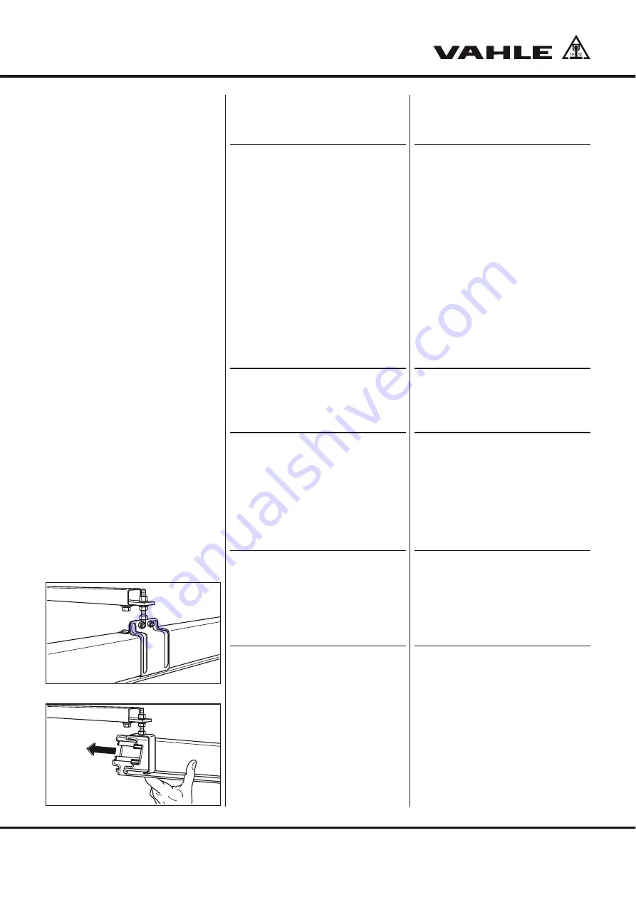
Schrauben Sie die Bolzen der Fest-
aufhängungen in die Aufhängeklam-
mern ein und befestigen Sie sie an
den Konsolen (
G1
).
Die zwei beiliegenden Unterlegscheiben
an den Aufhängebolzen der Fest- und
Gleitaufhängungen nur bei Befestigung
in Langlöchern verwenden.
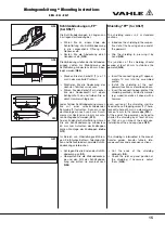
a) KBSL
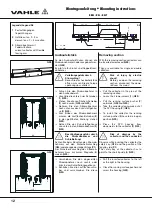
Befestigen Sie die einteiligen Gleit-
aufhängungen an den Konsolen.
Schieben Sie die Schleifleitung in die
Gleitaufhängung ein (
G2
).
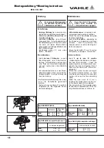
b) KSL, KSLT
Montieren Sie die Gleitaufhängungen
am nächsten Teilstück vor.
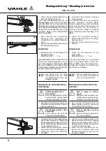
Mounting support brackets
Bolt EHK standard brackets or weld
steel angles with slotted holes.
H
Observe the following installa-
tion distances:
Max. support distance 2000 mm
for indoor and roofed outdoor
installations with a ambient tem-
perature upto 35 °C).
Max. 1333 mm for outdoor in-
stallations, special indoor
systems with high ambient
temperatures (>35-60 °C) and
systems with heating. The first
and last hanger must be placed
at least 250 mm and no more
than 500 mm from the end of a
powerail section. The distance of
the sliding hangers from the joint
material, end caps, feed points,
etc. must measure at least
250 mm and up to 500 mm to
guarantee free expansion (
S2
).
Installation of the powerail
Install the powerail straight and paral-
lel to the machinery track.
H
Free expansion of the powerail
away from the fixpoints must
be possible. Provisionally an-
chor the first powerail section
with two fixpoint hangers to fa-
cilitate the further mounting
procedure. These two fixpoint
hangers must be replaced by
sliding hangers after system in-
stallation has been completed.
If you install a straight run, install two
fixpoint hangers approximately at the
center of the system or in accordance
with the layout plan (
S1
) and (
S2
).
Screw the bolts into the clamps and
fix these to the brackets (
G1
).
Use the two washers of the fixpoint and
sliding hangers only for fixture in slotted
holes.
a) KBSL
Fix the solid sliding hangers to the
brackets.
Push the powerail into the sliding
hangers (
G2
).
b) KSL, KSLT
Pre-install the sliding hangers on the
next powerail section.
G1
G2
KBSL


