11
MKHF | MKHS
Montageanleitung
Mounting instructions
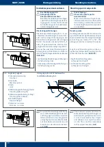
Federsteckverbinder
(nur bei MKHF)
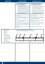
▸ Gleitend aufgehängte Teilstücke zuein-
ander schieben (
G11
)
Spring-loaded plug-in connector
(only for MKHF)
▸ Push sections with sliding suspension
together (
G11
)
G11
5-10 mm
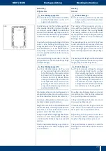
G12
G13
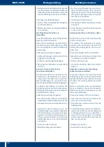
G14
G15
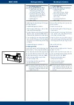
▸ Kupferschienenenden einzeln 5–10 mm in
die Federsteckverbinder einführen (
G12
)
▸ Beide Gehäuse so weit zusammenschie-
ben, bis eine mechanisch feste Verbin-
dung entsteht (
G13
)
S
Achtung!
Elektrische Verbindung
Die Federsteckverbinder müssen
vollständig einrasten, um die not-
wendige elektrische Verbindung zu
gewährleisten
▸ Insert the copper rail ends separately
5–10 mm into the spring-loaded plugin
connectors (
G12
)
▸ Push both housings together until a firm
mechanical connection is obtained (
G13
)
S
Caution!
Electrical Connection
The plug-in-joints have to snap in
completely to ensure the necessary
electrical connection
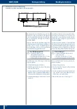
▸ Teilstücke nach außen ziehen, um die
Einrastung zu prüfen (
G14
)
▸ Pull both sections out of the housings
apart a little bit to check if the connectors
are snapped in correctly (
G14
)
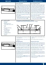
▸ Übergang der Kupferschienenstöße
durch Sicht- und Tastkontrolle prüfen
Der Übergang muss glatt, bündig und
ohne Grat sein, um eine Beschädigung
der Schleifkohlen des Stromabnehmers
zu vermeiden Max Abstand zwischen
den Kupferschienen: 2 mm (
G15
)
▸ Stromabnehmer einsetzen (vgl Kapitel
7 Stromabnehmer montieren, S 16) und
durch den Bereich fahren, um Unregel-
mäßigkeiten festzustellen
▸ Visually check the transition point of the
copper rail joints and also feel the transi-
tion point with your fingers as a check
The transition point must be smooth,
flush and have no burr so as to avoid
damage to the current collector’s carbon
brushes Max distance between the cop-
per rails: 2 mm (
G15
)
▸ Insert the current collector (cf chapter
7 Current Collectors, page 16) and move
through the area to detect irregularities


