background image

18


MKHF | MKHS 

Montageanleitung 

Mounting instructions

245

110

500

140 ± 10

stromlos

w/o cond.

G41

G40

0,8

- 1,

0m

3

2

1

5

7

4

6

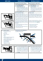
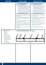
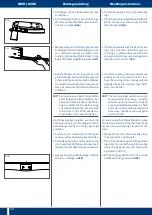
Verlegungsplan mit Schiebeweiche

Installation drawing incl.

Legende | Legend
1

   Streckeneinspeisung   


Line feed

2

   Kranbahn 


Machinery track

3

  Stoß  


Joint

4

   Überleitungseinführung  (gerade) 

Transfer guide (straight)

5

   Überleitungseinführung  (schräg) 

Transfer guide (oblique)

6

   Festaufhängung 


Fixpoint hanger

7

   Abstand  5–20 mm   

Distance  5–20 mm

350

70

stromlos

w/o cond.

165

B

G38

110

stromlos

w/o cond

.

205

350

B

G39

Sonderkomponenten montieren

B


Beschädigungsgefahr! 


Anlagenspezifische 


Dokumentation beachten!


Beachten Sie unbedingt die anlagen-

spezifischen Unterlagen wie den Ver-

legungsplan, in dem die Positionen 

für die Montage der Sonderkompo-

nenten festgelegt sind

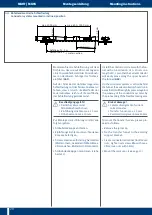
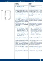
Überleitungseinführungen

Überleitungseinführungen gibt es in ver-

schiedenen Ausführungen für eine links- 

oder rechtsseitige Anbringung an der 

Stromschiene mit geradem oder schrägem 

Trichter Sie werden mit der Aufschrift „L“ 

oder „R“ gekennzeichnet Die Anschrä-

gungen werden werksseitig ausgeführt
Eine rechte oder linke Überleitungsein-

führung lässt sich bei Blick von hinten in 

den Trichter (B) folgendermaßen erkennen 

(

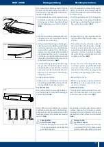
G38

/

G39

):

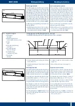
•  rechtsseitige Überleitungseinführungen: 

Sicherheitssteg links

•  linksseitige Überleitungseinführungen:

Sicherheitssteg rechts

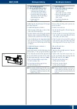
H

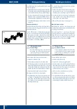
  An jeder Überleitungseinführung 

muss die Schleifleitung mit zwei Fest-

aufhängungen stabilisiert werden 

(Abstand 0,8 bis 1,0 m) Die geraden 

und gebogenen inneren Weichenteile 

auf dem Boden vormontieren und 

komplett an den Konsolen befesti-

gen (

G41

)


Mounting special components

B


Risk of damage!   


Observe the plant-specific   

documentation!  


Make sure to observe the plant-spe-

cific documents such as the installa-

tion drawing, in which the positions 

for mounting the special components 

are specified

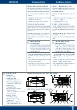
Transfer guides

Transfer guides are available in various de-

signs for left-hand or right-hand mounting to 

the conductor rail with a straight or oblique 

funnel They are marked “L“ or “R“ The 

oblique elements are made at the works  


A right or left transfer guide can be rec-

ognized as follows when looking into the 

funnel (B) from the rear (

G38

/

G39

): 


•  Right-hand transfer guides: 


safety web on the left

•  Left-hand transfer guides:  


safety web on the right

H

  The conductor systems must be sta-

bilised with two fixpoint hangers on 

each transfer guide (distance 08 to 

10 m) Pre-assembly the straight 

and oblique inner switch sections 

on the floor and fix completely 

to the support brackets (

G41

)  

Summary of Contents for MKHF

Page 1: ...MKHF MKHS Montage Wartung Mounting Maintenance 4c 2015...

Page 2: ...che und mechanische Installation 17 berleitungseinf hrungen 18 Einf hrungstrichter 19 Bel ftungsteilst ck 21 Dehnungsteilst ck 21 Content Information on the documentation 4 Additional documents 4 Symb...

Page 3: ...ck 31 Revisionsteilst ck 32 Inbetriebnahme 33 Wartung 33 Schleifleitung 33 Stromabnehmer 34 Heating 23 General 23 Installation guidelines 24 Simultaneous installation of the sections and heating cabl...

Page 4: ...rden k nnen und wie Sie diese Gef hr dung vermeiden k nnen H Tipp Hier erhalten Sie erg nzende Hin weise Information on the documentation Additional documents These mounting instructions and all ad di...

Page 5: ...omschienen immer auf einer ebenen Unterlage DieUmgebungstemperaturbeiTransport undLagerungdarf60 Cnicht berschrei ten Safety instructions Personnel qualifications Assembly installation and maintenance...

Page 6: ...n Beachten Sie unbedingt die anlagen spezifischen Unterlagen in denen die auftragsbezogenen Verlegungs pl ne den Anlagenaufbau abbilden General b Risk of pinching between mobile and fixed components Y...

Page 7: ...fen 2 werdengrund s tzlichzurKranbahnmontiert G01 H The safety lip 1 or the identification strips 2 are principally mounted towards the runway G01 Verlegungsbeispiele Installation drawing Aufh ngeabst...

Page 8: ...ngfestgesetzt werden Diese Aufh ngung muss nach Beendigung der Montage als Gleitaufh ngungausgef hrtwerden Installation of powerails Before installation please observe the plant specific installation...

Page 9: ...eratures 35 60 C andsystemswithheating The first and last hanger must be placed at least 250mm and no more than 500mm from the end of a powerail section The distance of the sliding hangers from the jo...

Page 10: ...r 63A 80A und 100A k nnen Federsteckverbinder verwendet werden G09 BeiSchleifleitungenMKHSf r140A 160A und 200A m ssen Schraubverbinder ver wendet werden G10 An den rechten Enden der Kupferschienen s...

Page 11: ...completely to ensure the necessary electrical connection Teilst cke nach au en ziehen um die Einrastung zu pr fen G14 Pull both sections out of the housings apartalittlebittocheckiftheconnectors are...

Page 12: ...le the black pvc caps by pull ing the two locking lugs apart G16 G16 G17 G18 G19 5 10 mm G20 Sicherungsb gelseitlichausbauen G17 Federsteckverbinder von den Kupfer schienen abkippen G18 Die Montage de...

Page 13: ...obtained G21 S Caution Electrical Connection The plug in joints have to snap in completely to ensure the necessary electrical connection Check the seat of the connectors at the copper rail joint by p...

Page 14: ...staufh ngung in direkter N he zur Ein speisung max 5m vorsehen oder nach Allgemeiner Verlegungsplan S 6 mit Gleitaufh ngungen und flexiblem Kabel anschluss anbringen so dass eine Aus dehnung von 75mm...

Page 15: ...saufklebern Kunststoffwinkel auf das Geh useende stecken Schrauben Sie die Kabelschuhe an die Gewindewstifte in der Reihenfolge Ka belschuhe F cherscheiben Sechskant muttern G32 Ziehen Sie die Sechska...

Page 16: ...eningtorquesforthescrewcon nection max 10 Nm 1 L1 L2 max 10 Nm G34 L1 3 L3 6 1 2 2 5 L2 1 4 Kennzeichnung Steuerleitung for control unit 1 2 G35 M Verschraubung so weit anziehen bis das Kabel abgedich...

Page 17: ...er herstellen Es gibt eine Ausf hrung zur Montage an einemRohrmitAdapterblechoderQuadrat Hohlprofil A und zur Montage an einer ebenen Fl che B G37 Electrical and mechanical installation S Risk of dama...

Page 18: ...nten in den Trichter B folgenderma en erkennen G38 G39 rechtsseitige berleitungseinf hrungen Sicherheitssteg links linksseitige berleitungseinf hrungen Sicherheitssteg rechts H An jeder berleitungsein...

Page 19: ...strichter Sicherheitssteg rechts H An jedem Einf hrungstrichter muss die Schleifleitung mit zwei Festauf h ngungen stabilisiert werden Ab stand 0 8 bis 1m S Risk of damage Observe the safety instructi...

Page 20: ...kkappen montieren siehe Seite 13 Install the conductor systems with the fun nel with an inclination of 5 10mm on a lengthof2 3msothatthecurrentcollector will easily move along the upper bevel of the f...

Page 21: ...st ck Beispiel Installation drawing with anti condensation section example Legende Legend 1 Endkappe End cap 2 Bel ftungsteilst ck Anti condensation section 3 Halle Hall 4 Streckeneinspeisung Line fee...

Page 22: ...nce If distance a is too small the conductor systems will be de formed at higher temperatures and the current collector will jam If distance a is too large the ex pansion section can slide out of the...

Page 23: ...eizdrahttypen und unterschiedlichen L ngen verwendet werden Die f r die Heizdrahtverlegung erforderli chen Angaben sind dem Verlegungsplan zu entnehmen Heating General SRisk of damage The heating syst...

Page 24: ...nteur damitsichimSto bereichbeim VerschiebenkeineSchlaufebildenkann Installation guidelines At least two persons are required for the installation The installation can be per formed much faster with t...

Page 25: ...n je nach Beheizungsl nge ist dieserVorgangmehrfachzuwiederholen Then the heating wires have to be pulled through by about 5 meters The other sections have to be mounted in the same way The heating wi...

Page 26: ...durch den zweitenMonteur an den Einlaufstellen einzuleiten Austausch des Teilst cks Wiedermontage der Heizkabel For the second power feed section at the end of the heating circuit the heat ing wires h...

Page 27: ...eplace heating cables proceed as fol lows Completely remove the heating cable according to page 26 Reinstall the heating cable Installation in the terminal box The left and right feed is appropriate f...

Page 28: ...on the 1 5mm2 connecting cable 3 by a length of about 6mm G51 Take the ends of the heating cable and connecting cable from which the insu lation has been removed and plug it into the serial connector...

Page 29: ...a rig gleichzeitigmontiert wiehierbeschrie ben k nnen aber auch nacheinander einzeln eingezogen werden Unter 10m Einzeldichtlippenl nge wird die Dichtlippe von Hand eingebracht Ab 10m L nge liegt jede...

Page 30: ...freien Sitz achten Falls erforderlich das Profil wieder zu r ckziehen und erneut einziehen Bei Anlagenl ngen gr er als 40m die Sto verbindung von Teill ngen mittels Verbindungslaschen 2 teilig wie fol...

Page 31: ...to facilitate the entry of the current collector and fix suitably as before G60 Zur berpr fung der korrekten Montage die gesamte Schleifleitung mit einem Stromabnehmer durchfahren Hierbei besonders au...

Page 32: ...two housing sections can be pushed together Now there is enough space at each end of the section to push the bolted joints completely onto the copper G63 B Lebensgefahr durch Stromschlag Die Schleifl...

Page 33: ...rry out a trial run Observe the follow ing points First run at low speed The carbon brushes must run in the conductorsystemswothoutvibrations Avoid sparking at the carbon brushes indication of soiled...

Page 34: ...ung tragen Stromabnehmer AmStromabnehmersindfolgenderegelm igeKontroll undWartungsarbeitenn tig B Wear protective clothing Wear suitable breathing protection against dust development during cleaning w...

Page 35: ...bei Betriebsspannungen 50V inkl PE bei Oxidation Kontroll und Wartungsarbeiten Zeitpunkt Schleifkohlen austauschen Bei Errei chen der Verschlei markierung max 5mm Checks and maintenance work Interval...

Page 36: ...ptik 7b 8 Leitungswagen und Leitungen Leitungswagen f r Laufschiene 8a Leitungswagen f r Flachleitungen auf Laufschiene 8b Leitungswagen f r Rundleitungen auf Laufschiene 8c Leitungswagen f r Laufschi...

Reviews: