SMGM SYSTEM
82
8.9
Configuration: Segment lengths
The length of an SMGM rail segment depends on the following parameters:
•
Number of mobile couplers
•
Length and type of the HF cable (coax) being used on the vehicle
•
Length and type of the HF cable (coax) being used on the stationary side
•
Number of expansion joints located in the segment
A minimum level, which must be limited to adhere to the EMC restrictions, is required for the flawless intended
communication operation.
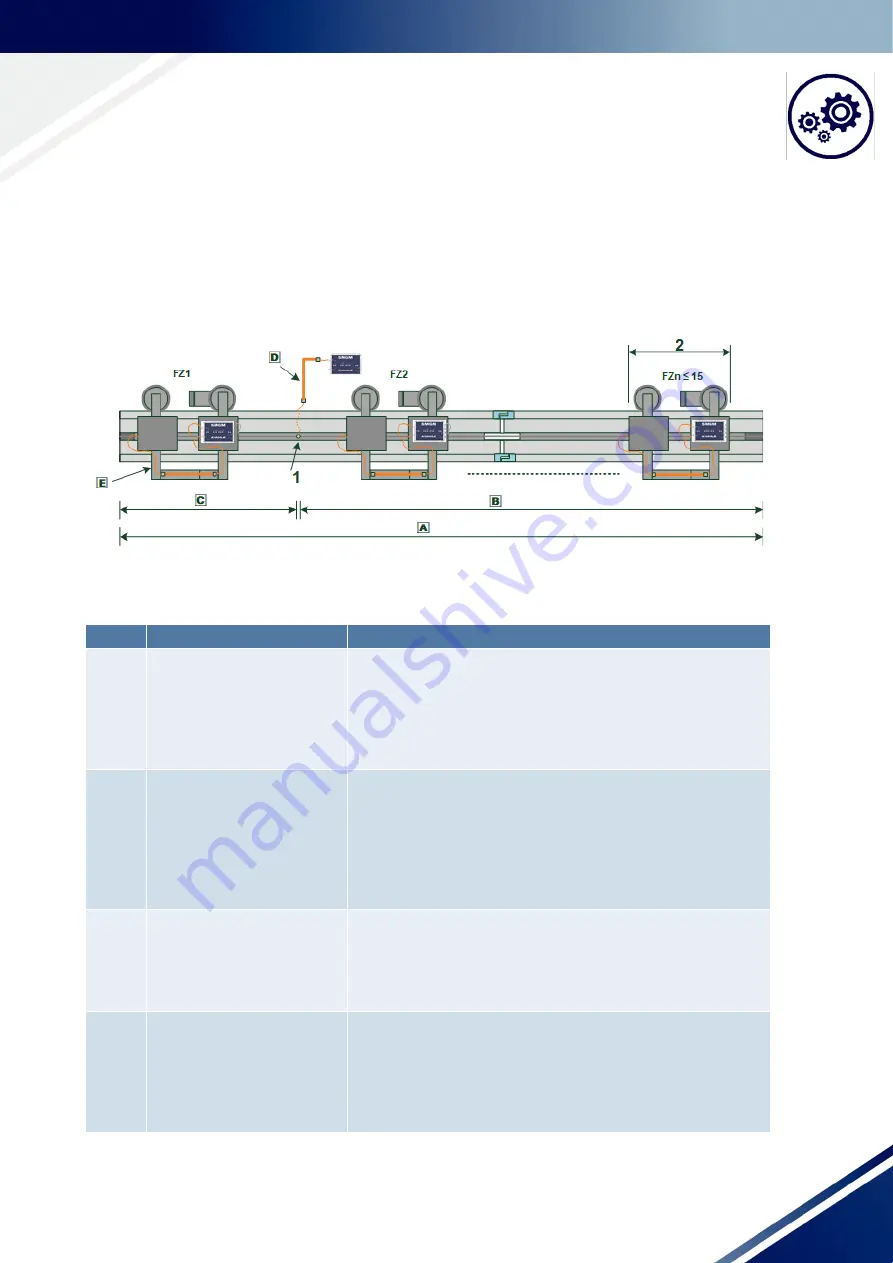
Fig. 8-16 Schematic diagram SMGM segments
1: Stationary coupler
2: Vehicle length
Position Designation
Description
A
Segment length
A maximum of 15 mobile device interfaces can be operated on an
SMGM rail segment. Communication interferences will occur if
more than 15 participants are present in the segment.
The maximum segment length must be mechanically smaller than
15 x vehicle lengths.
Segment length A
≤
15 x vehicle length
B/ C
Sub-segment length B/C
The stationary coupler defines the sub-segment lengths B and C.
The maximal possible number of vehicles, i.e. the mobile coupler
in a sub-segment, determines the longer sub-segment B or C.
MAX NUMBER OF COUPLERS
If a SEGMENT is fed at the start/end, then one sub-segment is
equivalent to the SEGMENT LENGTH.
D
Coaxial cable lengths station-
ary
The coaxial cable lengths are determined by the installation point
of the SMGM-SI interfaces. The lengths to determine the damping
value of the stationary coaxial cables.
COAX DAMPING STATIONARY
E
Coaxial cable mobile
The coaxial cable lengths are determined by the installation point
of the SMGM-DI interfaces. The lengths influence the damping val-
ue of the mobile part. The coaxial cable with the higher damping
value is used to determine the COAX DAMPING MOBILE.
COAX DAMPING MOBILE


