SMGM MODULES
28
6.3
Connections and displays
6.3.1
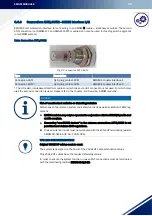
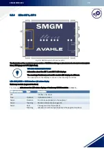
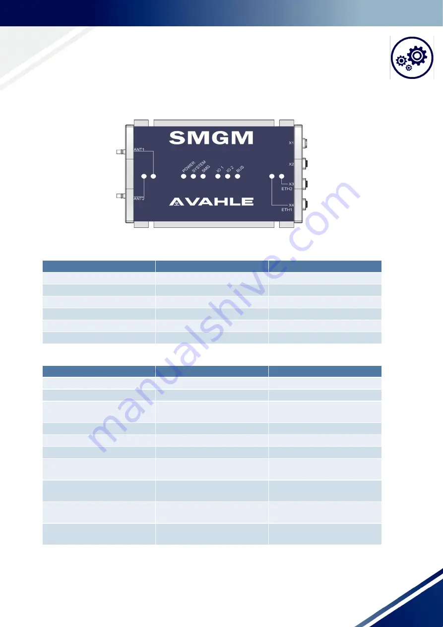
SMGM modules: Dark-blue front
Module overview
Fig. 6-2 View of SMGM module (Standard/Advanced/Cross-system)
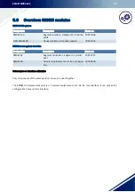
Overview: Connections
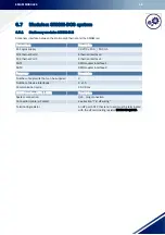
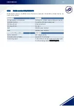
Overview: LED displays
*Depending on the module type - see the LED status displays chapter
Connection
Function
Description
X1
Power supply 24VDC
M12, A-coded, 8-pole, pin
X2
RS485 Interface
M12, A-coded, 4-pole, bushing
X3
Ethernet Port 1
M12, D-coded, 4-pole, bushing
X4
Ethernet Port 2
M12, D-coded, 4-pole, bushing
ANT1
SMGM coupler Connection 1
QLS, bushing
ANT2
SMGM coupler Connection 2
QLS, bushing
Item
Function
Description
POWER
Supply voltage
24 VDC On
SYSTEM
System status display
System status/error
SMG
SMG Status
SMG interface status display/con-
figuration error
IO1
*
*
IO2
*
*
BUS
*
*
ETH2
Ethernet Port 2 - Link
Ethernet Port Link/Activity/
100Mbps Link
ETH1
Ethernet Port 1 - Link
Ethernet Port Link/Activity/
100Mbps Link
ANT1
SMG Antenna 1
SMG Interface - no segment/seg-
ment/active
ANT2
SMG Antenna 2
SMG Interface - no segment/seg-
ment/active


