COMMISSIONING
58
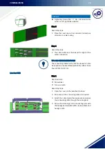
Step 5
Assembly steps:
1. Push the connector cover cap onto one side of
the section as far as it will go.
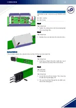
Step 6
Assembly steps:
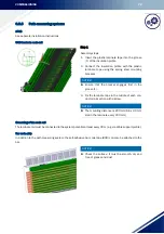
1. Insert the next section from the front into the
hanger and snap it into place.
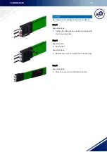
Step 7
Assembly steps:
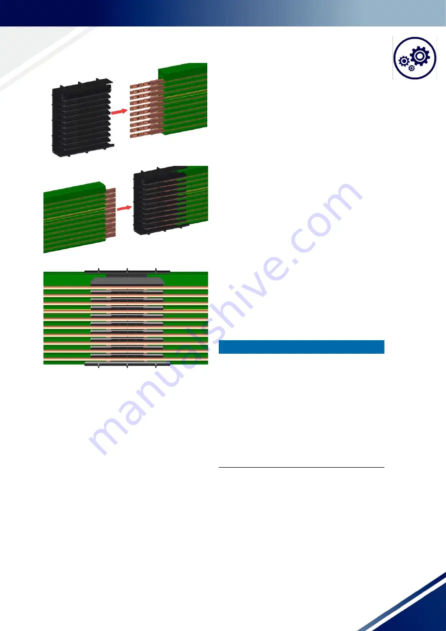
1. Push the two sections together until the connec-
tors are plugged in. To do this, cover the free end
of the conductor system with an impact protec-
tion and drive the sections together using a ham-
mer to setting dimension "A" (table page 60).
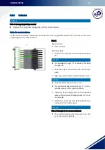
NOTICE!
►
You can use an installation comb to precisely ad-
just the air gap in the copper. It is inserted be-
tween the copper conductor rails. Depending on
the air gap required
(0
- 5 mm), the various installation combs can be
used (e.g. at an installation temperature of 20°
C, the air gap is
(„A“
= 2
mm).
►
To make assembly easier, an assembly tool can
be used for the connecting joint for installation in
the HRL support profile.
Summary of Contents for VKS10
Page 89: ...MAINTENANCE 87 Connecting caps mast assembly before Connecting caps mast assembly after ...
Page 96: ...PROTECTIVE MEASURES 94 10 PROTECTIVE MEASURES 10 1 EU conformity declaration ...
Page 99: ...CE Technical Documentation DQS certified in accordance DIN EN ISO 9001 2015 OHSAS 18001 2007 ...


