COMMISSIONING
59
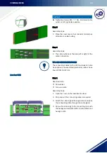
Step 8
Required tools:
⚒
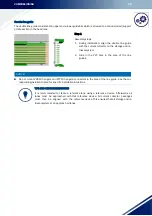
Plastic block
⚒
Assembly tool (mounting fork for connecting
joint)
Assembly steps:
1. Slide the plastic block over the copper ends.
Then insert the assembly tool into the slotted
holes of the HRL support profile and slide the
section against the other section.
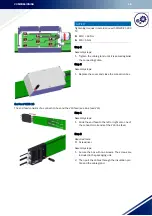
Step 9
Prerequisites:
Ensure that the connectors are inserted correct-
ly.
Required tools:
⚒
Assembly tool (mounting fork for connecting
cap))
Assembly steps:
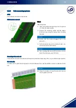
1. Align the connecting cap properly using the as-
sembly tool, which places the cap correctly over
the joint.
NOTICE!
►
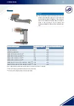
The setting dimensions according to Table Table of plug connector assignments must only be strictly ob-
served if the maximum temperature range (- 10° C to + 40°
C) is to be expected for the conductor system.
To simplify installation at lower temperature differences (t
<
20°
C), the conductor system can be pushed
together so that that a closed copper joint is created. The air gap at the insulating housings then adjusts
itself automatically.
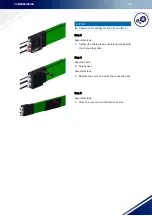
Step 10
Assembly steps:
1. Install the other sections in the same way.
NOTICE!
►
The distance between the hangers and the connecting caps, feed terminals etc. has to be min. 50 mm to
not hinder expansion.
Summary of Contents for VKS10
Page 89: ...MAINTENANCE 87 Connecting caps mast assembly before Connecting caps mast assembly after ...
Page 96: ...PROTECTIVE MEASURES 94 10 PROTECTIVE MEASURES 10 1 EU conformity declaration ...
Page 99: ...CE Technical Documentation DQS certified in accordance DIN EN ISO 9001 2015 OHSAS 18001 2007 ...


