VDF730
User
Manual
Operation
and
Display
-
71
-
closed
(
NC
)
terminal
,
and
TC
is
a
normally
open
(
NO
)
terminal
.
You
can
defne
the
functions
of
the
DO
terminals
by
setting
P3
-
01
and
P3
-
02
to
indicate
the
running
state
and
alarm
information
of
the
AC
drive
.
There
are
a
total
of
20
functions
.
For
details
,
see
the
descriptions
of
group
P3
.
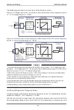
Terminal
Corresponding
Function
Code
Output
Feature
Description
FM
-
COM
P3
-
05
when
P3
-
00
=
0
Transistor
,
able
to
output
high
-
speed
pulses
of
50
KHz
;
drive
capacity
:
24
VDC
,
50
mA
P3
-
04
when
P3
-
00
=
1
Transistor
;
drive
capacity
:
24
VDC
,
50
mA
P3
-
05
when
P3
-
00
=
2
Output
voltage
:
0
–
10
V
Output
current
:
0
–
20
mA
TA
-
TB
-
TC
P3
-
01
Relay
;
drive
capacity
:
250
VAC
,
3
A
PA
-
PC
P3
-
02
When P5
-
00
=
0
,
the FM terminal is high
-
speed pulse output
.
The frequency of output
pulses
indicates
the
value
of
the
internal
running
parameters
.
The
greater
the
value
is
,
the
higher
the
output
pulse
frequency
is
.
The
100
%
value
corresponds
to
100
kHz
.
The
property
of
the
indicated
internal
parameter
is
defned
by
P5
-
06
.
4
.
10
Use
of
AI
Terminals
The
AC
drive
supports
a
total
of
two
AI
terminals
.
The
AI
can
provide
the
voltage
or
current
for
frequency
source
setting
,
torque
setting
,
PID
setting
or
feedback
source
,
and
can
also
be
used
as
DI
.
The
relationship
between
the
physical
quantities
and
the
voltage
corresponding
setting
or
current
corresponding
setting
is
set
in
P2
-
08
to
P2
-
19
.
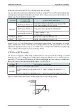
Terminal
Input
Signal
Characteristic
AI1
-
GND
It
receives
the
signal
of
0−10
VDC
.
AI2
-
GND
If
J2
is
connected
to
the
position
with
"
V
"
mark
,
it
receives
the
signal
of
0−10
VDC
.
If
J2
is
connected
to
the
position
with
"
I
"
mark
,
it
receives
the
signal
of
4−20
mA
.
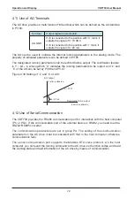
Figure
4
-
29
Relationship
between
analog
input
and
corresponding
setting
Corresponding
setting
(
frequency
and torque
)
AI
0
.
0
%
0V
(
0mA
)
P2
-
12
(
AI2
)
P2
-
09
P2
-
08
P2
-
10
Relay
;
drive
capacity
:
250
VAC
,
3
A
Summary of Contents for VDF730 Series
Page 1: ...VDF730 Series...
Page 7: ......
Page 8: ...1 Safety Information and Precautions...
Page 15: ...Safety Information and Precautions VDF730 User Manual 14...
Page 16: ...2 Product Information...
Page 30: ...3 Mechanical and Electrical Installation...
Page 51: ...Mechanical and Electrical Installation VDF730 User Manual 50...
Page 52: ...4 Operation and Display...
Page 75: ...Operation and Display VDF730 User Manual 74...
Page 76: ...5 Function Code Table...
Page 97: ...Function Code Table VDF730 User Manual 96...
Page 98: ...6 Description of Function Codes...
Page 153: ...Description of Function Codes VDF730 User Manual 152...
Page 154: ...7 EMC...
Page 158: ...8 Troubleshooting...


