Installation and maintenance instructions ecoTEC plus 937 0020031552_06
27
2
1
3
6
2
4
5
1
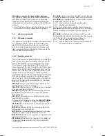
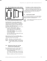
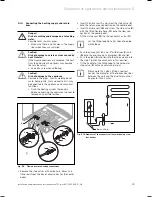
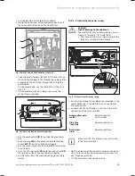
Fig. 5.6 Gas connection
Proceed as follows for gas connection:
Remove the gas connection pipe elbow (
2
) and gas
isolator valve (
1
) from the packaging.
Push the union nut (
3
) and the olive (4) onto the gas
pipe which protrudes from the combi boiler.
Push the gas isolator valve (
1
) onto the gas pipe
which protrudes from the combi boiler up to the stop.
Pull the union nut (
3
) with the olive (
4
) towards the
gas isolator valve. Tighten the union nut hand tight.
Push the union nut (
6
) and the olive (
5
) onto the gas
connection pipe elbow (
2
).
Push the gas connection pipe elbow (
2
) into the gas
isolator valve (
1
) up to the stop.
Pull the union nut (
6
) with the olive (
5
) towards the
gas isolator valve. Tighten the union nut hand tight.
The diameter of the pre-formed copper pipe (
2
) is
22 mm. Connect this pipe to a gas supply pipe having
a diameter of not less than 22 mm.
i
The gas supply pipework must be of sufficient
size so that, at maximum output, a gas pres-
sure of 20 mbar is available at the input to
the combi boiler.
Tighten all connections.
Purge the gas pipe before commissioning.
Check the gas connection for leaks using leak-detect-
ing spray.
>
>
>
>
>
>
>
>
>
>
>
5.12
Connecting the hot and cold water
a
Danger!
Risk of scalding and damage due to leaking
water.
Possible leaks in water pipes.
Make sure there is no tension in the supply
lines when they are installed.
b
Caution!
Risk of damage to gas shut-off valves
caused by heat transfer.
If the final connections are soldered, the heat
transferred during the process may damage
the gas shut-off valves.
Use extra care when soldering.
b
Caution!
Risk of damage to the appliance.
Residue in the pipes, such as welding beads,
scale, hemp, putty, rust and coarse dirt, may
be deposited in the appliance and cause mal-
functions.
Flush the cold water inlet pipe thoroughly
before connecting the appliance in order to
remove any residue that may be there.
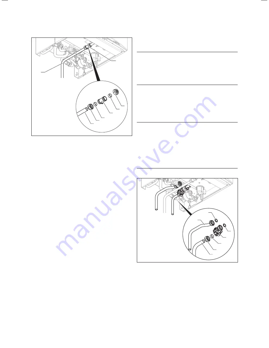
1
2
3
4
5
6
7
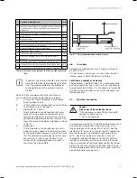
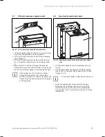
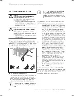
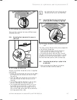
Fig. 5.7 Installing the cold water and hot water connections
Remove the two copper tails (
5
,
6
) for water connec-
tion, the cold water isolating valve (
2
) and the union
nut (
4
), olive (
3
) and fibre seals (
1
,
7
) from the pack-
aging.
Insert the fibre seal (
1
) and screw the cold water iso-
lating valve (
2
) to the cold water connection of the
shift load storage tank.
>
>
>
>
>
Sequence of operations during installation 5
Summary of Contents for ecoTEC plus 937
Page 1: ...For the heating engineer Installation and maintenance instructions GB IE ecoTEC plus 937 VUI...
Page 74: ...74 Installation and maintenance instructions ecoTEC plus 937 0020031552_06...
Page 76: ...76 Installation and maintenance instructions ecoTEC plus 937 0020031552_06...
Page 77: ...Installation and maintenance instructions ecoTEC plus 937 0020031552_06 77...
Page 78: ......
Page 79: ......
Page 80: ...0020031552_06 GBIE 102010 Subject to alterations...

