Installation and maintenance instructions ecoTEC plus 937 0020031552_06
35
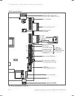
X 2
BUS
— +
24V
7 8 9
230V
L N 3
4 5
X 20
X40
X3
1
X12
X41
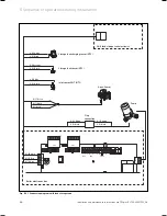
Electronics box
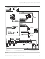
Hot water
outlet (NTC)
Fan
Ignition electrode
Flow temperature
sensor (NTC)
Diverter valve
Gas valve
Water pressure sensor
Return temperature
sensor (NTC)
X 20/5 red
X 20/7 black
X 20/7 black
X 20/8 blue
X 2/12 green
X 2/11 red
X 2/9 black
Pump
X 20/18 red (24 VDC)
X 20/9 blue (Erde)
X 20/16 blue (Earth)
X 20/13 black
X 20/12 black
X 20/4 grey (PWM)
X 20/3 black (Hall-Signal)
X 20/17 red (24 VDC)
X 2/15 brown C
X 2/8 blue D
X 2/16 black A
X 2/7 pink B
X 2/3 red (+ 5V)
X 2/2 black (Earth)
X 2/6 Green (Signal)
X 2/5 violet (Signal)
X 2/1 black
Plate
heat exchanger
(NTC)
X 2/4 orange
X 2/10 black
Thermal fuse
Plug
connection
Fig. 5.20 Connection diagram combi boiler
Sequence of operations during installation 5
Summary of Contents for ecoTEC plus 937
Page 1: ...For the heating engineer Installation and maintenance instructions GB IE ecoTEC plus 937 VUI...
Page 74: ...74 Installation and maintenance instructions ecoTEC plus 937 0020031552_06...
Page 76: ...76 Installation and maintenance instructions ecoTEC plus 937 0020031552_06...
Page 77: ...Installation and maintenance instructions ecoTEC plus 937 0020031552_06 77...
Page 78: ......
Page 79: ......
Page 80: ...0020031552_06 GBIE 102010 Subject to alterations...

