Installation and maintenance instructions ecoTEC plus 937 0020031552_06
37
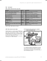
5.20 Control
units
5.20.1 Vaillant control units and accessories
Controller
Item no.
Connection
VRC 400 (1-circuit controller, weather-controlled)
00 2001 0843
Installation in electronics box (plug-and-play)
VRT 360 (room temperature controller)
00 2001 0842
Wall-mounted, 2-wire bus
VRT 360f (room temperature controller)
00 2001 8258
Wireless controller, receiver wall-mounted
VRT 230 (room temperature controller)
00 2001 0841
Wall-mounted, 3-wire connection to terminals 3-4-5
timeSWITCH 140 (timer)
306 760
Installation in electronics box (plug-and-play)
timeSWITCH 130 (timer)
306 759
Installation in electronics box (plug-and-play)
VRT 30 (room thermostat)
300 637
Wall-mounted, 3-wire connection to terminals 3-4-5
VRT 30 (room thermostat)
0020018265
Wall-mounted, 2-wire bus
Telecommunication
Item no.
Connection
vrnetDIALOG 830 (Int)
00 2000 3988
GSM/GPRS, installation in electronics box (plug-and-play)
vrnetDIALOG 860/2 (Int)
00 2000 3984
Wall-mounted, GSM/GPRS, up to 16 appliances
Accessories
Item no.
Connection
VR 65 control centre for UK cylinder installation (eBUS)
307 215
System solution for UK cylinder connection
vrDIALOG 810/2
00 2002 3370
Diagnostic software
Table 5.1 Vaillant control units and accessories
5.20.2 External electrical controllers
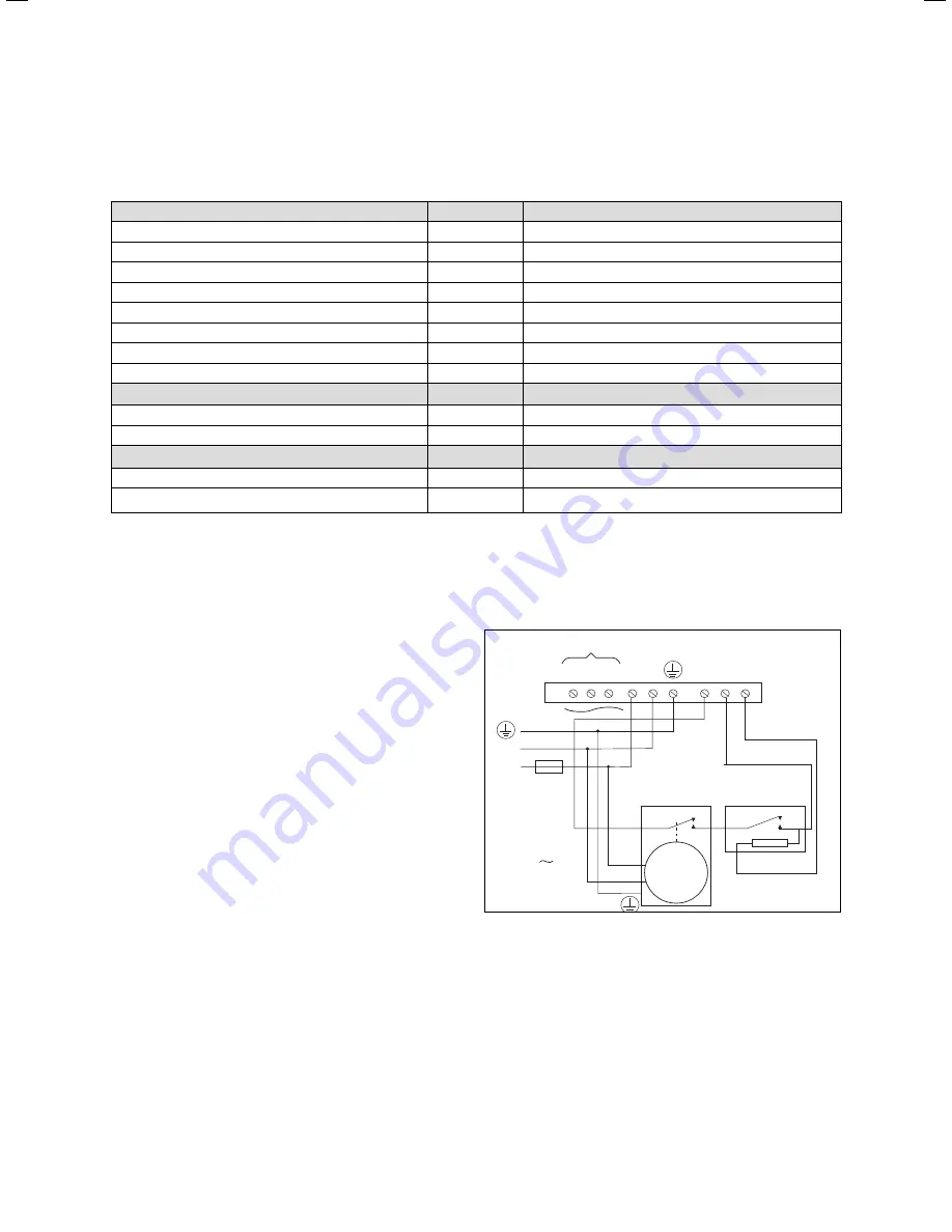
The boiler terminals 3, 4 and 5 on the combi boiler are
for the connection of external controllers, for example a
timer and/or a room thermostat. Terminals 3 and 4 are
linked together from the factory. If external controllers
are used, this link must be removed and the controllers
must be connected to terminals 3 and 4.
Terminal 5 is an additional neutral line for example for
the anticipator of a room thermostat.
5.20.3 Details for the connection of an external
timer to the terminal strip
3
9
8
7
POWER SUPPLY
230 V
50 Hz
L
L
L N
N
N
N
20 VDC
(DO NOT USE 7, 8, 9 IN UK!)
FUSE 3 A
SWITCH
CONTACTS
ROOM
THERMOSTAT
TIMER
4 5
Fig. 5.22 Details for the connection of timers
If it is intended to connect a room thermostat in addi-
tion to a timer, the connection between the ON connec-
tion of the timer and terminal 4 on the combi boiler
must be broken by the contacts of the room thermostat
(see circuit diagram Fig. 5.22).
Sequence of operations during installation 5
Summary of Contents for ecoTEC plus 937
Page 1: ...For the heating engineer Installation and maintenance instructions GB IE ecoTEC plus 937 VUI...
Page 74: ...74 Installation and maintenance instructions ecoTEC plus 937 0020031552_06...
Page 76: ...76 Installation and maintenance instructions ecoTEC plus 937 0020031552_06...
Page 77: ...Installation and maintenance instructions ecoTEC plus 937 0020031552_06 77...
Page 78: ......
Page 79: ......
Page 80: ...0020031552_06 GBIE 102010 Subject to alterations...

