Installation and maintenance instructions ecoTEC plus 937 0020031552_06
43
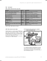
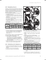
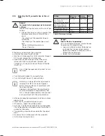
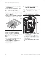
6.9.2 Checking the gas flow rate
The boiler is fitted with a multifunctional automatic gas
valve which ensures that the precise air/gas ratio is pro-
vided under all operating conditions. The gas flow rate
has been set during production and does not require
adjustment. With the front casing fitted check the gas
flow rate of the boiler as follows:
Start the boiler by activating the test program P.1 as
described in section 9.2.
In addition, ensure that maximum heat can be dissi-
pated into the heating system by turning up the room
thermostat.
Alternatively, fully open the hot water taps to ensure
full flow rate through the boiler.
Wait at least 5 minutes until the boiler has reached
its operating temperature.
Ensure that all other gas appliances in the property
are turned off.
Measure the gas flow rate at the gas meter.
Check that the gas flow rate is as stated in Table 6.1.
Nominal net
heat input in
kW
as per
BS EN 483
Gas flow rate
Natural gas in m
3
/h
Propane in kg/h
n 5 % - 10 % n 5 % - 10 %
37.8
4.00
4.20
3.60
2.94
3.09
2.65
Table 6.1 Gas flow rate
If the measured gas flow rate lies outside the toler-
ance limits specified in Table 6.1, do not operate the
boiler and inform the Vaillant Service Solutions
(0870 6060 777).
If the measured gas flow rate is within the tolerance lim-
its shown in Table 6.1, then proceed as follows:
Take the boiler out of operation by
Pressing the “
+
” and “
i
” buttons simultaneously
and turn down both thermostat control knobs.
Allow the boiler to cool down by turning off water
taps and allow pump overrun to operate for a mini-
mum of two minutes.
Record the boiler maximum gas flow rate onto the
Benchmark gas boiler commissioning checklist.
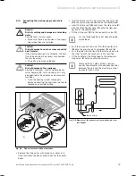
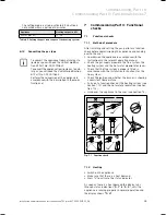
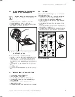
6.9.3 Checking the gas inlet working pressure
Ensure that the gas inlet working pressure can be
obtained with all other gas appliances in the property
working.
Remove the front casing from the boiler.
Close the gas isolation valve of the boiler.
>
>
>
>
>
>
>
>
>
–
–
>
>
>
>
1
2
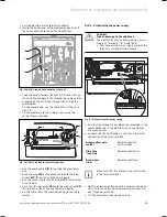
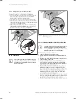
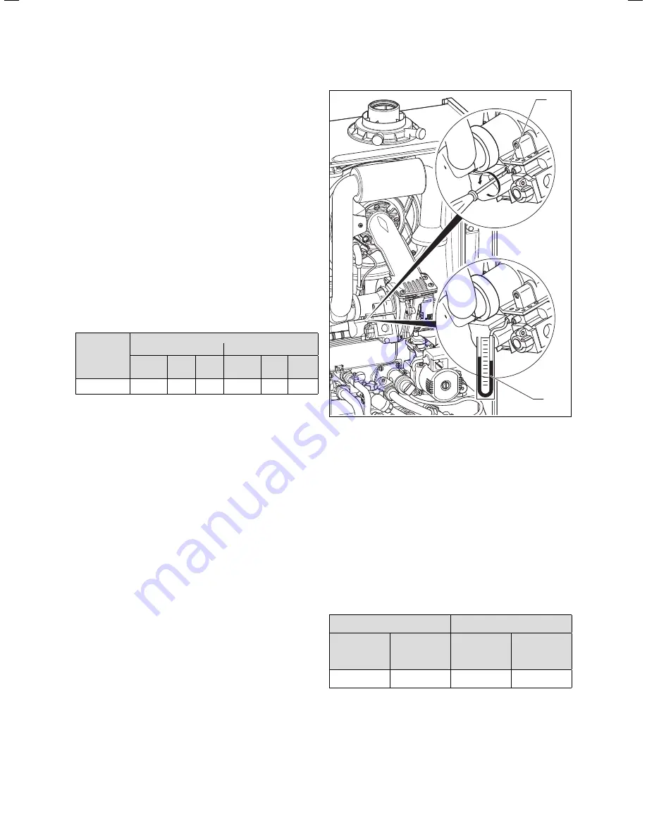
Fig. 6.7 Measuring the gas inlet working pressure
Loosen the sealing screw marked “
in
” (
1
) on the gas
valve.
Connect a digital pressure gauge or U-tube manome-
ter (
2
).
Open the gas isolation valve of the boiler.
Start the boiler by activating the test program “
P.1
”
as described in section 9.2.
In addition, ensure that maximum heat can be dissi-
pated into the heating system by turning up the room
thermostat.
Alternatively, fully open the hot water taps to ensure
full flow rate through the boiler.
With the boiler operating at full load check that the
gas inlet working pressure at the reference test
point (
1
) complies with the requirements of Table 6.2.
Natural gas (G20)
LPG (G31)
Minimum
pressure at
reference test
point in mbar
Maximum
pressure at
reference test
point in mbar
Minimum
pressure at
reference test
point in mbar
Maximum
pressure at
reference test
point in mbar
15
23
23
43
Table 6.2 Gas inlet working pressures at the reference test
point
Should the pressure recorded at the reference test
point in the boiler be lower than indicated (Table 6.2)
>
>
>
>
>
>
>
>
Commissioning, Part I 6
Summary of Contents for ecoTEC plus 937
Page 1: ...For the heating engineer Installation and maintenance instructions GB IE ecoTEC plus 937 VUI...
Page 74: ...74 Installation and maintenance instructions ecoTEC plus 937 0020031552_06...
Page 76: ...76 Installation and maintenance instructions ecoTEC plus 937 0020031552_06...
Page 77: ...Installation and maintenance instructions ecoTEC plus 937 0020031552_06 77...
Page 78: ......
Page 79: ......
Page 80: ...0020031552_06 GBIE 102010 Subject to alterations...

