50
Installation and maintenance instructions ecoTEC plus 937 0020031552_06
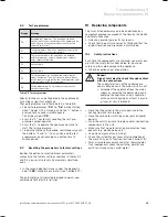
Always perform the following steps
prior
to inspection
or maintenance work:
Switch off the main switch.
Disconnect the boiler from the power mains by
disconnecting the mains plug or
de-energising the boiler via an isolating device with
a contact opening of at least 3 mm (e. g. fuses or
power switches).
Further check for electrical isolation of the appliance
by use of a test meter.
Close the gas isolation valve.
Close the service valves in the heating flow and
return.
Remove the front casing from the boiler.
When removing any water carrying components
ensure that water is kept away from all electrical
components.
Always perform the following steps after performing
any inspection or maintenance work:
Always use new seals and O-rings when parts are
replaced.
Open the service valves in the heating flow and
return.
Reconnect the boiler to the power mains.
Switch the main switch on.
Fill the heating circuit of the boiler to a pressure of
between 1.0 and 2.0 bar if required.
Bleeding the heating installation (see section 6.4, Fill-
ing and bleeding the heating system).
Open the gas isolation valve.
Check the boiler for gas and water leaks.
If necessary, refill and re-bleed the heating installa-
tion.
Replace the front casing to the boiler.
Carry out a functional check of the boiler
(see section 7).
Always check earth continuity, polarity and resist-
ance to earth with a multimeter after any service
work and after replacing any electrical component.
8.1.3 Checking
the
CO
2
concentration
i
Checking/adjustment of the CO
2
concentra-
tion is required in the following instances:
- replacement of gas valve,
- conversion to or from Natural Gas/LPG
- or if an incorrect combustion is suspected.
>
>
–
–
>
>
>
>
>
>
>
>
>
>
>
>
>
>
>
>
>
4
3
2
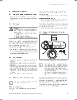
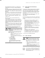
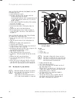
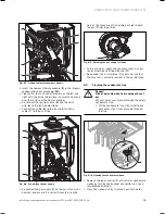
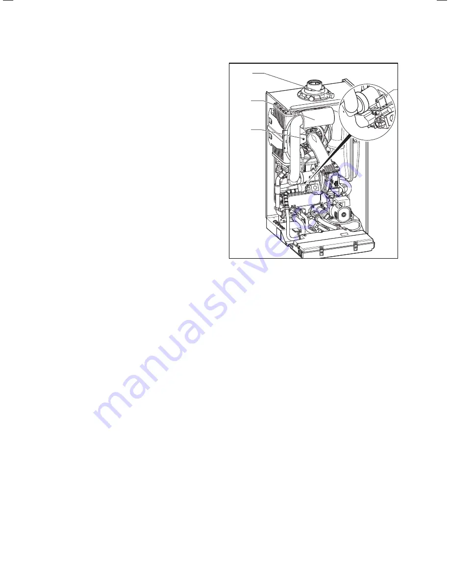
Fig. 8.1 Measuring the CO
2
concentration, specifying the air
ratio (gas setting)
Legend:
1 Main
throttle
2 Screw
3 Air
intake
pipe
4 Flue gas analysis point
i
The boiler is fitted with a flue gas analysis
point (
4
). A suitable flue gas analyser can be
connected to this point to establish the com-
bustion performance of the boiler.
Remove the front casing.
Start the testing program P.1.
Wait at least 5 minutes until the boiler reaches its
operating temperature.
Measure the CO
2
concentration at the flue gas analy-
sis point (
4
). Compare the measured value with the
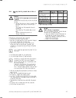
corresponding value in Table 8.1.
If all these points are as required, proceed as
described in section 7.8.5.
If one of the flue gas values is greater than the
acceptable values in Table 8.1, then proceed as
described in the following section 8.1.4.
>
>
>
>
>
>
8 Inspection and maintenance
Summary of Contents for ecoTEC plus 937
Page 1: ...For the heating engineer Installation and maintenance instructions GB IE ecoTEC plus 937 VUI...
Page 74: ...74 Installation and maintenance instructions ecoTEC plus 937 0020031552_06...
Page 76: ...76 Installation and maintenance instructions ecoTEC plus 937 0020031552_06...
Page 77: ...Installation and maintenance instructions ecoTEC plus 937 0020031552_06 77...
Page 78: ......
Page 79: ......
Page 80: ...0020031552_06 GBIE 102010 Subject to alterations...

