62
Installation and maintenance instructions ecoTEC plus 937 0020031552_06
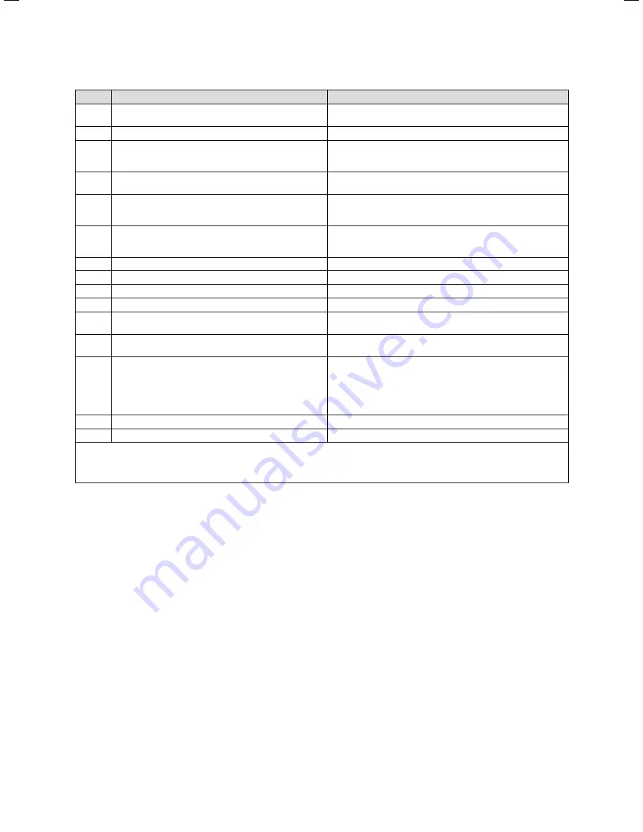
Display
Meaning
Displayed value/settable value
d.72
Pump overrun time after warm start or shift load storage
tank charging
Setting range in seconds: 0, 10, 20 to 600
Factory setting: 80
d.73
Offset for warm start target temperature
Setting range: -15 K to +5 K (Factory setting: 0K)
d.74
Legionella protection shift load storage tank
Setting range:
0 = deactivated
1 = activated (Factory setting)
d.75
Maximum charging duration for an external cylinder with-
out its own control (system boilers only)
Adjustment range in min: 20, 21, 22 to 90 (Factory setting: 45)
d.77
Part load of the external cylinder (limit for charging
capacity of the external cylinder, system boilers only)
Adjustment range in kW: appliance specific
Factory setting: max. output
d.78
Limit for charging temperature of the external cylinder
(target flow temperature in storage tank mode, system
boilers only)
Adjustment range in °C 55 to 85 (Factory setting: 80)
d.80
Operating hours heating
in h
d.81
Operating hours hot water generation
in h
d.82
Operating cycles in heating mode
number/100
1)
(3 equals 300)
d.83
Cycles in hot water operation
number/100
1)
(3 equals 300)
d.84
Maintenance indicator: Number of hours until the next
maintenance
Setting range: 0 to 3000h and „-“ for deactivated
Factory setting: „-“ (300 corresponds to 3000h)
d.88
switching on threshold for recognizing water tapping
(only VCW)
0 = 1,5 l/min and no delay,
1 = 3,7 l/min and 2s delay
d.92
Module recognition shift load storage tank
Setting range:
0 = not recognised
1 = no communication via PE-BUS; Module recognised earlier
2 = Communication OK
Setting = 0: Unregister shift load storage tank from combi boiler
(if shift load storage tank is to be de-installed, set d.92 = 0)
d.93
DSN appliance variant setting
Setting range: 0 to 99
d.96
Factory reset
1 = Resetting adjustable parameters to factory setting
1)
In the diagnostic codes 80 to 83 5 digit figure values are stored. When selecting e.g. d.80 only the first two digits of the figure value
are displayed (e.g.10). By pressing the „i“ key, the display switches over to the last three figures (e.g. 947). The operating hours coun-
ter of the heating in this case would be 10947 h. Pressing the „i“ again causes the display to switch back to the diagnosis point that
was called up.
Table 9.3 Diagnosis codes of the second diagnosis level (con-
tinued)
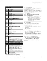
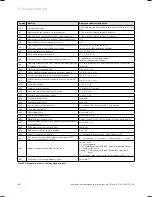
9.1.3 Error codes
Fault codes take priority over all other display functions
in the event of a system fault occurring.
If many errors occur simultaneously, the relevant error
codes are displayed alternately for approx. 2 seconds
each.
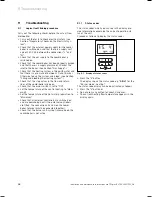
9.1.4 Fault
memory
The fault memory of the unit stores the information
concerning the last ten errors.
Press the "
i
“ and „
-
“ buttons simultaneously.
Scroll backwards with button "
+
“ through the list of
stored errors.
You can exit the error memory display as follows:
Push the button "
i
“under the display, or
Do not press any button for about 4 minutes. The dis-
play then switches back to the display of current flow
temperature.
>
>
>
>
9 Troubleshooting
Summary of Contents for ecoTEC plus 937
Page 1: ...For the heating engineer Installation and maintenance instructions GB IE ecoTEC plus 937 VUI...
Page 74: ...74 Installation and maintenance instructions ecoTEC plus 937 0020031552_06...
Page 76: ...76 Installation and maintenance instructions ecoTEC plus 937 0020031552_06...
Page 77: ...Installation and maintenance instructions ecoTEC plus 937 0020031552_06 77...
Page 78: ......
Page 79: ......
Page 80: ...0020031552_06 GBIE 102010 Subject to alterations...

