Installation and maintenance instructions ecoTEC plus 937 0020031552_06
65
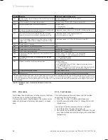
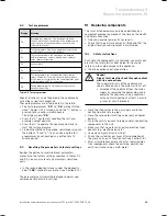
9.2 Test
programmes
Display
Meaning
P.0
Bleeding test program. The heating circuit and
the hot water circuit are bled via the automatic air
vent (the cap of the automatic air vent must be
released two turns).
P.1
Test programme where the appliance is operated
in full load after successful ignition.
P.2
Test program where the appliance is operated
with minimum gas volume (ignition gas volume)
after successful ignition
P.3
not available
P.4
not available
P.5
Test programme for checking the safety tempe-
rature limitation: The unit is heated by avoidance
of the regular switch-off by the feed regulator until
a temperature of 97 °C is reached.
P.6
Filling programme: The diverter valve moves to
the centre position.
Table 9.5 Test programmes
Special functions can be triggered in the appliance by
activating various test programs.
These programmes are listed in detail in Table 8.5.
The test programmes “
P.0
” to “
P.6
” will be started
when " Power ON“ is turned on and the "+“ button is
pressed for 5 seconds simultaneously.
The display shows "
P.0
“.
Press the "
+
" key to start counting the test pro-
gramme number upwards.
Press the "
i
“ to operate the appliance now and to
start the test programme.
To de-activate the setting mode, simultaneously push
the buttons "
i
“ and "
+
“. You can also end the test
programmes by not pushing any button for a 15
minute period.
9.3
Resetting the parameters to factory settings
Besides the option to reset individual parameters
manually to the factory settings specified in Tables 9.2
and 9.3, you can also reset all parameters simultane-
ously.
In the second diagnostic level, under the diagnostic
point "d.
96
" change the value to 1 (see Section 9.1.2).
The parameters of all adjustable diagnosis points now
correspond to the factory settings.
>
>
>
>
>
10 Replacing
components
The tasks listed below may only be undertaken by a
competent engineer approved at the time by the Health
and Safety Executive.
Only use genuine spare parts for repairs.
Check that the parts are correctly fitted and that the
original location and alignment is maintained.
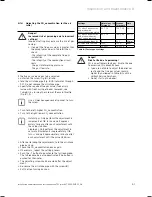
10.1 Safety
instructions
Each time the components are replaced, you must com-
ply with the safety instructions below for your own
safety and to avoid damage to the appliance.
Take the appliance out of operation.
e
Danger!
Risk of fatal electric shock through contact
with live connections.
The supply terminals of the appliance are
under voltage even if the mains switch is off.
Disconnect the appliance from the mains
supply by removing the power plug or de-
energise the appliance using a separator
with a contact opening of at least 3 mm (e.
g. fuses or circuit breakers).
Close the stop valves in the gas supply and in the
heating flow and return pipes.
Close the cold water inlet stop valve (only on combi
boilers).
Drain the unit if you wish to replace water-conducting
components in the unit.
Make sure that no water drips on live electrical com-
ponents (e.g. electronic box etc.).
Use only new gaskets and O-rings.
Check the system for gas leaks after completion of
the work. Carry out a function test (see Section 7.8).
After all maintenance work and after replacing elec-
trical components check the earthing, polarity and
earth resistance using a multi-meter.
>
>
>
>
>
>
>
>
>
>
>
Troubleshooting 9
Replacing components 10
Summary of Contents for ecoTEC plus 937
Page 1: ...For the heating engineer Installation and maintenance instructions GB IE ecoTEC plus 937 VUI...
Page 74: ...74 Installation and maintenance instructions ecoTEC plus 937 0020031552_06...
Page 76: ...76 Installation and maintenance instructions ecoTEC plus 937 0020031552_06...
Page 77: ...Installation and maintenance instructions ecoTEC plus 937 0020031552_06 77...
Page 78: ......
Page 79: ......
Page 80: ...0020031552_06 GBIE 102010 Subject to alterations...

