70
Installation and maintenance instructions ecoTEC plus 937 0020031552_06
2
1
5
4
3
6
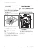
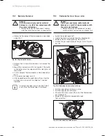
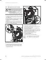
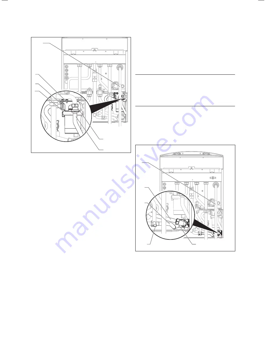
Fig. 10.8 Replacing storage tank pump
Remove the discharge pipe (
1
) of the heating pres-
sure relief.
Lower the electronics box as described in Sec-
tion 5.19.2.
Unclip the back cover of the electronics box and
swing the cover upwards to reveal the connections.
Pull the plug
X12
off the electronic printed circuit
board.
Pull the free end of the line carefully through the
entry grommets on the combi boiler and on the shift
load storage tank.
Release the sensor wire of the pump from the wiring
harness by pulling the plug off the wiring harness.
Unscrew the sheet metal bracket (
6
) from the chas-
sis.
Release the fitting (
2
) on the connector pipe (
3
).
Release the spring clamp (
5
) on the storage tank
charging pump casing (
4
).Support the storage tank
charging pump with your other hand to prevent it
from falling out of the chassis.
Pull the storage tank charging pump out of the chas-
sis downwards.
Fit the pipe bracket to the new storage tank charging
pump using new gaskets.
Fit the new storage tank charging pump in reverse
order and use new gaskets.
Connect the electrical wires of the pump in reverse
sequence. Check for correct routing of the lines.
Re-fit the discharge pipe (
1
) and use new gaskets.
Filling and vent the combi boiler and the shift load
storage tank.
>
>
>
>
>
>
>
>
>
>
>
>
>
>
>
After completion of the work check the system for
gas leaks and carry out a function test (see Section
8.8).
10.8
Replacing the aqua sensor
a
Danger!
Risk of personal injury and/or material
damage as a result of non-compliance with
the safety instructions.
Before replacing the component, comply
with the safety instructions in Chapter 10.1.
Isolate the unit from the mains as described in Sec-
tion 10.1.
Close the gas isolator valve in the gas supply pipe.
Close the stop valves in the hot water system and
drain the water out of the combi boiler and the shift
load storage tank.
3
2
5
4
1
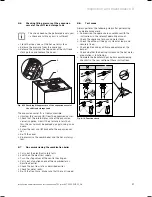
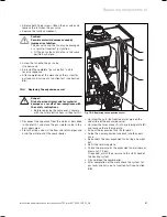
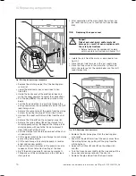
Fig. 10.9 Replacing the aqua sensor
Remove the discharge pipe (
1
) of the heating pres-
sure relief.
Separate the electrical wire of the aqua sensor from
the wiring harness by pulling off the plug from the
wiring harness.
Release the fitting (
2
) and (
3
) on the elbows (
4
)
and (
5
).
Turn the Aqua-Sensor slightly to the side and pull the
Aqua-Sensor downwards out of the chassis.
Remove the pipe elbow from the Aqua-Sensor.
>
>
>
>
>
>
>
>
>
>
10 Replacing components
Summary of Contents for ecoTEC plus 937
Page 1: ...For the heating engineer Installation and maintenance instructions GB IE ecoTEC plus 937 VUI...
Page 74: ...74 Installation and maintenance instructions ecoTEC plus 937 0020031552_06...
Page 76: ...76 Installation and maintenance instructions ecoTEC plus 937 0020031552_06...
Page 77: ...Installation and maintenance instructions ecoTEC plus 937 0020031552_06 77...
Page 78: ......
Page 79: ......
Page 80: ...0020031552_06 GBIE 102010 Subject to alterations...

