Installation and maintenance instructions ecoTEC plus 937 0020031552_06
71
Replacing components 10
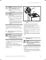
Fit the pipe elbow onto the new Aqua-Sensor and use
new gaskets.
Mount the new Aqua-Sensor in reverse order and
replace the seals.
Connect the line plug of the Aqua-Sensors with the
wiring harness.
Re-fit the discharge pipe (
1
) and use new gaskets.
Filling and vent the combi boiler and the shift load
storage tank.
After completion of the work check the system for
water leaks and carry out a function test (see Sec-
tion 8.8).
10.9
Replacing the electronics on the shift load
storage tank
a
Danger!
Risk of personal injury and/or material
damage as a result of non-compliance with
the safety instructions.
Before replacing the component, comply
with the safety instructions in Chapter 10.1.
Isolate the unit from the mains as described in Sec-
tion 10.1.
Close the gas isolator valve in the gas supply pipe.
Comply with the assembly and installation manuals
provided with the spare parts.
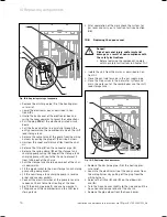
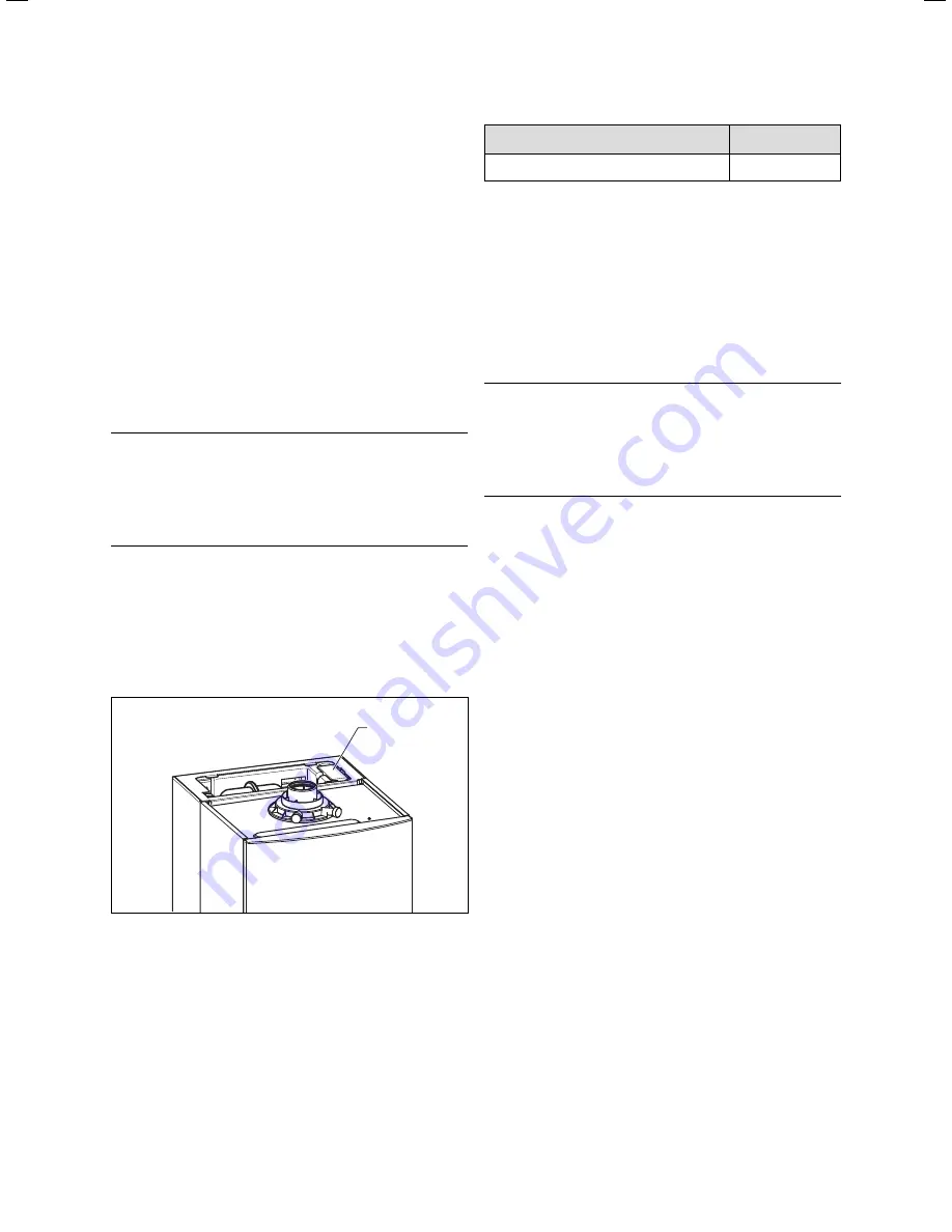
Remove the screw on the top cover of the shift load
storage tank and remove the cover.
1
Fig. 10.10 Replacing electronics
Pull the electronics (
1
) out of the location slot.
Pull off the plug connector from the wiring harness.
Fit the new electronics in reverse order.
Start up the appliance.
Check the correct setting of the unit variants (DSN) as
follows:
Enter the 2nd diagnostic level of the combi boiler.
Set the equipment-specific DSN value (parameter
"
d.93
“) in accordance with Table 10.1.
>
>
>
>
>
>
>
>
>
>
>
>
>
>
>
>
>
Appliance type
DSN
ecoTEC plus 937
8
Table 10.1 DSN Setting Values
Exit the diagnostic mode.
The combi boiler ecoTEC plus 937 is ready for opera-
tion.
10.10 Replacing the electronics and display on the
combi-heater
a
Danger!
Risk of personal injury and/or material
damage as a result of non-compliance with
the safety instructions.
Before replacing the component, comply
with the safety instructions in Chapter 10.1.
Comply with the assembly and installation manuals
provided with the spare parts.
Replacing the display or the electronics
If you are only replacing one of the two components the
parameter settings take place automatically. When
switching the unit on the new component automatically
takes the pre-set parameters from the components
which have not been changed.
Replacing the display or the electronics
When replacing both components, after being turned on,
the appliance goes to fault and displays the error mes-
sage
F.70
.
In the second diagnostic level, under the diagnostic
point "d.
93
" enter the number of appliance variant
according to Table 9.1 (see Chapter 9.9).
The electronics is now set to the appliance type and the
parameters of all adjustable diagnostic points corre-
spond to the factory settings.
>
>
>
>
Summary of Contents for ecoTEC plus 937
Page 1: ...For the heating engineer Installation and maintenance instructions GB IE ecoTEC plus 937 VUI...
Page 74: ...74 Installation and maintenance instructions ecoTEC plus 937 0020031552_06...
Page 76: ...76 Installation and maintenance instructions ecoTEC plus 937 0020031552_06...
Page 77: ...Installation and maintenance instructions ecoTEC plus 937 0020031552_06 77...
Page 78: ......
Page 79: ......
Page 80: ...0020031552_06 GBIE 102010 Subject to alterations...

