6
0020149478_06
Los soportes que no estén fijos pueden volcar y provocar
accidentes con los consiguientes daños personales graves.
Existe riesgo de vuelco al subir a un soporte que no esté
fijo.
Los soportes no entrañan riesgo de vuelco únicamente si se
han instalado conforme a las instrucciones y están
completamente equipados.
>
Asegúrese de que el lugar de instalación es lo
suficientemente estable para no poner en peligro la
seguridad.
>
Asegúrese de que los soportes tengan suficiente
estabilidad y que estén dotados de pies de apoyo.
>
No utilice los soportes como elemento auxiliar para el
ascenso.
>
Fije los soportes a la pared o al suelo.
>
Instale tantos pies de apoyo como considere necesario.
Peligro de muerte por salida de gases.
La existencia de fugas en la tubería de gas puede provocar
asfixia o derivar en una explosión.
>
Antes de la puesta en marcha de la instalación,
compruebe que los conductos de gas sean estancos y no
presenten fugas.
Existe peligro de muerte si faltan los dispositivos de
seguridad.
La falta de algún dispositivo de seguridad (como la válvula
de seguridad o el vaso de expansión) puede tener como
consecuencia quemaduras u otras lesiones mortales al
producirse, por ejemplo, una explosión.
>
Monte en la instalación los dispositivos de seguridad
necesarios.
>
Informe al usuario sobre cuál es la función y en qué
posición se encuentran los dispositivos de seguridad.
>
Al realizar la instalación de soportes, calefactores,
reguladores y del gas, tenga en cuenta las leyes, normas
y directivas nacionales e internacionales
correspondientes.
>
Observe también las normas e indicaciones de
instalación que acompañan a cada uno de los aparatos.
En una instalación en cascada utilice trampillas anti-retorno
para gases de combustión solo motorizadas o solo
mecánicas. No está permitida la combinación de trampillas
antiretorno para gases de combustión.
Las indicaciones de estas instrucciones sobre el soporte y
las medidas de altura solo son válidas para los sistemas de
evacuación de gases de combustión de Vaillant.
GB - Information
These instructions show how to assemble and install
cascade systems that contain the following boilers: ecoTEC
VU GB 466/4-5, VU GB 656/4-5, VU GB 806/5-5,
VU GB 1006/5-5 or VU GB 1206/5-5.
The numbers in the following drawings specify the article
numbers for the components. The numbers in the square
brackets specify the set in which the component can be
found.
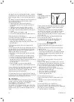
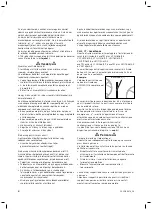
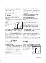
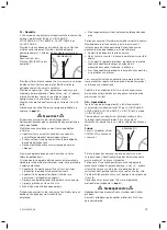
Example:
The component with article
number 0020140011 is
included in set 1.
0020140011 [1]
Article numbers that do not specify the set refer to other
Vaillant products. Components without article numbers
must be provided on-site.
The figures in the top-left of each drawing provide the
sequence of the work steps. A letter added to the figures
(e.g. „a“) shows an alternative work step that is only
required for the configuration variants that are also shown
in the header bar.
You can find an overview of all possible configuration
variants starting from page 16.
Gas isolator cocks with the designation TAE have an
integrated fire protection device (
¬
Section 4
).
e
Danger
a
Risk of death from electric shock!
Touching live connections may cause serious personal
injury.
The electrical installation must only be carried out by a
competent person.
>
Observe all safety information in the installation
instructions for components of the heating installation.
>
Switch off the power supply before commencing the
installation work.
>
Secure the power supply against being switched on
again.
Falling racks may lead to accidents that cause serious
personal injury.
There is a risk of tipping if you climb on racks. The racks
are therefore only secured against tipping once they have
been installed correctly and have been fully equipped.
>
Ensure that the installation location satisfies the static
conditions and has sufficient stability.
>
Ensure that the racks are sufficiently stable and are
aligned with the adjustable feet.
>
Do not use the racks as climbing aids.
>
Secure the racks to the wall or floor.
>
Install all required rack feet.
Risk of death due to escaping gas!
Leaks in the gas pipe may lead to asphyxiation or to an
explosion.
>
During start-up, check that the entire gas pipe is
leaktight.
Risk of death due to lack of safety devices!
A lack of safety devices (e.g. expansion relief valve,
expansion vessel) may lead to potentially fatal scalding and
other injuries, e.g. due to explosions.
>
Install the necessary safety devices.
Summary of Contents for ecoTEC VC 1006/5
Page 16: ...16 0020149478_06 C A D L H1 H2 H3 H4 1694 580 431 H1 H2 H3 H4 C A D L 363 1694 580...
Page 18: ...18 0020149478_06 H1 H2 1694 L 580 D B A C 431 H1 H2 1694 L 580 D B A C 363...
Page 20: ...20 0020149478_06 231 K 23 431 C A B 580 D E X Y F G J 231 23...
Page 22: ...22 0020149478_06 231 G F Y J 231 X D 580 E B A K 23 H C...
Page 24: ...24 0020149478_06 1 26 2 32 3 40 4 43 5 47 6 49...
Page 25: ...0020149478_06 25 7 52 8 56 9 59 10 60 11 65...
Page 29: ...0020149478_06 29 1 1 7a 1 7b 1 8a 1 8b 1 8c...
Page 31: ...0020149478_06 31 1 303960 1 11c 45 65 kW...
Page 39: ...0020149478_06 39 2 2 13a 2 13b 2 13c...
Page 42: ...42 0020149478_06 3 3 5a 3 5b 3 5c 3 5d 3 5e 3 5f...
Page 45: ...0020149478_06 45 4 4 4 4 5 4 6...
Page 46: ...46 0020149478_06 4 4 7...
Page 51: ...0020149478_06 51 6 DN100 0020151875 13 DN100 0020139996 13 6 5...
Page 52: ...52 0020149478_06 7 7 3 7 1a 3 7 1b 3 7 1c 3 7 1d...
Page 53: ...0020149478_06 53 7 7 2 1 2 7 3a 1 2 7 3b 7 3c 1 2 7 3d...
Page 54: ...54 0020149478_06 7 7 4a 7 4b 2 1 7 4c 7 5a 7 5b...
Page 55: ...0020149478_06 55 7 2 1 7 5c 7 5d 1 2 7 6a 1 2 7 6b 1 2 7 6c...
Page 60: ...60 0020149478_06 10 10 M8 x 65 61 0020140039 61 10 1 2x 2x 10 2...
Page 63: ...0020149478_06 63 10 VC VM VU 45 65 kW 130 0020042909 10 8c 10 9 A B 10 10 61 61...
Page 64: ...64 0020149478_06 10 10 11...
Page 65: ...0020149478_06 65 11 11 0020141331 73 11 1a 0020141331 73 11 1b 0020141331 73 11 1c...
Page 70: ...70 0020149478_06 11 0020141327 75 0020141326 75 11 9c...
Page 71: ......
Page 72: ...0020149478_06 INT 112016 Subject to change Manufacturer 0020149478_06...


